Appendix F – On-Board LED Functionalities and CPU MMI Modes
204
www.qualitrolcorp.com
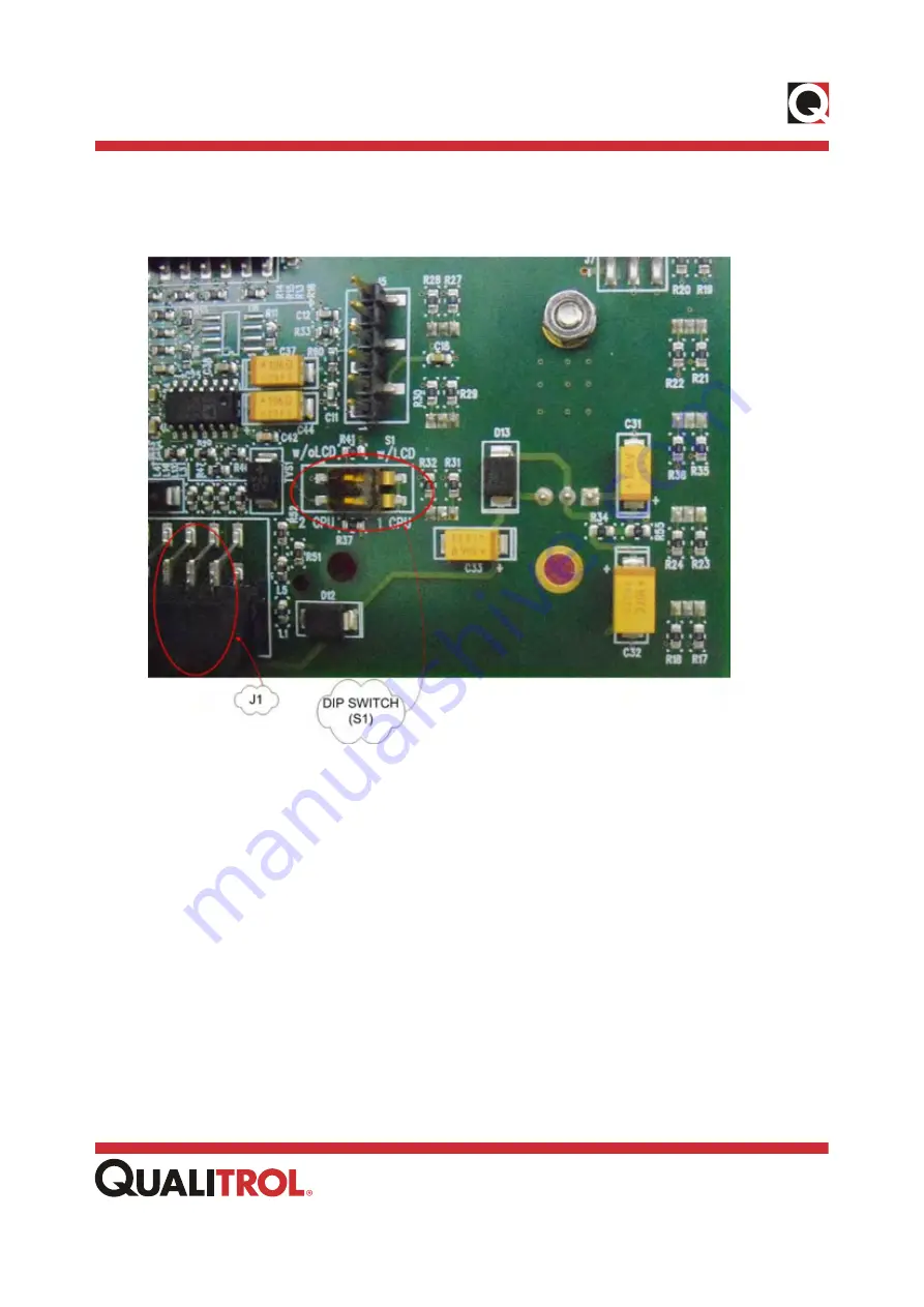
In the 1 CPU mode, the CPU must be connected to the first UART port (refer to legend J1
on MMI card).
Figure F.3 – MMI Card – Dip Switch (S1) and First UART Port (J1)
If the CPU is connected to the second UART port (J2 on MMI card), then the connection will
not be detected because the second UART port is not initialized in the 1 CPU mode.
Summary of Contents for INFORMA PMD-A
Page 1: ...User Manual www qualitrolcorp com INFORMA PMD A Data Acquisition Unit Document ID 40 08557 01...
Page 7: ...Contents Contents iv www qualitrolcorp com References 240...
Page 8: ...About This Manual 1 www qualitrolcorp com Chapter 1 About This Manual...
Page 12: ...Overview 5 www qualitrolcorp com Chapter 2 Overview...
Page 15: ...Components and Specifications 8 www qualitrolcorp com Chapter 3 Components and Specifications...
Page 58: ...Installation 51 www qualitrolcorp com Chapter 4 Installation...
Page 86: ...Configuration 79 www qualitrolcorp com Chapter 6 Configuration...
Page 108: ...Configuration 101 www qualitrolcorp com Figure 6 22 PQ Free Interval Continuous Recording...
Page 120: ...Maintenance 113 www qualitrolcorp com Chapter 7 Maintenance...
Page 126: ...Maintenance 119 www qualitrolcorp com Figure 7 7 Voltage Calibration...
Page 166: ...Appendix B INFORMA PMD A Functions 159 www qualitrolcorp com Figure B 9 RMS Envelope PQRVC...
Page 199: ...Appendix D License Information 192 www qualitrolcorp com Appendix D License Information...
Page 246: ...References 239 www qualitrolcorp com References...


