background image

2

Parts LIst

Mounting bracket .................................................................................................. 1
Screws   ................................................................................................................ 4
Wall anchor ........................................................................................................... 4

INstaLLatIoN

Tools required: 

•  Electric drill 

•  Phillips (cross-head) screwdriver 

•  Tape measure

Choose a suitable location for mounting the convector:

A.  The location shall have enough space and clearance as illustrated in Fig. 1.

B.   The power outlet shall be accessible by the electrical cord of this convector without 

using an extension cord.

C.  The power outlet shall not be located directly behind or above the convector.
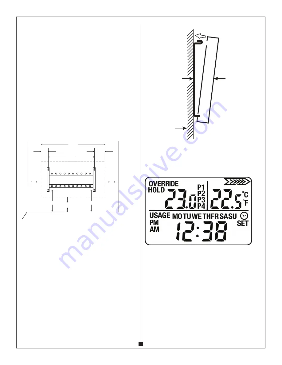
Fig. 1

WIDTH OF CONVECTOR

6 in

(15.3 cm)

6 in

(15.3 cm)

Minimum

clearance to 

adjacent 

surface

6 in

(15.3 cm)

Minimum

clearance to 

adjacent 

surface

Minimum

distance 

to ground

58.1 cm

33.7 cm

9.8 cm

14.6 cm

22.2 cm

22.2 cm

waLL MoUNtING INstrUCtIoNs

1.  Release the mounting bracket by pressing the locking brackets on both sides.

2.   Use the mounting bracket as a template by holding it against the wall as illustrated 

in Fig. 1.

3.   Follow the dimensions specified in Table 1 and place mounting bracket in the 

desired location.

4.   Mark the 4 screw holes. Place mounting bracket on the screw markings and ensure 

the mounting bracket is perfectly level. 

5.   Predrill holes and insert 4 wall anchors. Wall anchors are needed for mounting on 

drywall or concrete walls. Ensure you use the proper anchors for your wall type.

6.  Replace the mounting bracket and fasten it with screws (minimum 4 screws).

7.   Mount the convector to the mounting bracket and engage the 2 locking brackets at 

the top. See Fig. 2.

CAuTION – hIgh TeMPeRATuRe, RIsk Of fIRe. keeP eleCTRICAl CORds, 

dRAPeRy, fuRNIshINgs ANd OTheR COMbusTIbles AT leAsT 3 fT (0.9 M) 

AWAy fROM The fRONT Of The heATeR ANd AWAy fROM The sIde ANd Of 

heATeR.
WARNINg – TO ReduCe RIsk Of fIRe, dO NOT sTORe OR use gAsOlINe OR 

OTheR flAMMAble VAPORs ANd lIquIds IN The VICINITy Of The heATeR.

Fig. 2

Wall

Wall bracket

Convector

oPeratIoN

Turn the “0/I” switch on the right side of the convector to “I” position. The indicator light 
and display will be ON.

1.  Time setting –  Press MODE button and press UP and DOWN buttons at the same 

time. 

  A.  Press the UP or DOWN button to set the ‘DAY’ from MONDAY (MO) – TUESDAY 

(TU) – WEDNESDAY (WE) – THURSDAY (TH) – FRIDAY (FR) – SATURDAY (SA) – 
SUNDAY (SU).

  B.   Press MODE button again. The display ‘HOUR’ will flash and then press the UP or 

DOWN button to set the ‘HOUR’.

  C.   Press MODE button again. The display ‘MINUTE’ will flash and then press the UP 

or DOWN button again to set the ‘MINUTE’.

  D.  Press MODE button again to exit and save the setting.

Summary of Contents for MCVT120-150

Page 1: ...ny ventilation or exhaust openings as this may cause an electric shock fire or may damage the heater Do not use on soft surfaces such as a bed where openings may become blocked 9 To prevent possible fire do not block air intakes or exhaust in any manner 10 Heaters may have hot and sparking parts inside Do not use it in areas where gasoline paint or flammable liquids are used or stored 11 Use this ...

Page 2: ... Predrill holes and insert 4 wall anchors Wall anchors are needed for mounting on drywall or concrete walls Ensure you use the proper anchors for your wall type 6 Replace the mounting bracket and fasten it with screws minimum 4 screws 7 Mount the convector to the mounting bracket and engage the 2 locking brackets at the top See Fig 2 CAUTION HIGH TEMPERATURE RISK OF FIRE KEEP ELECTRICAL CORDS DRAP...

Page 3: ...ain to set the HOUR of by pressing the UP and DOWN button E Press the MODE button again to set the MINUTE of time by pressing UP and DOWN button F Press the MODE button again and repeat the steps in C to E to set the temperature and time of P2 to P4 E g P1 Temperature 25 C time 6 00 AM P2 Temperature 20 C time 8 00 AM P3 Temperature 25 C time 6 00 PM P4 Temperature 18 C time 11 00 PM The convector...

Page 4: ...use abrasive cleaners or spray liquids on the unit surfaces Note It is possible that the unit surface may discolour yellow over time due to dust or cigarette smoke This is normal and not a manufacturing defect STORAGE When the heater is not in use the heater shall be stored in a dry location away from possible damage The power cord should be stored properly to avoid contact with hot or sharp objec...

Page 5: ...5 ...

Page 6: ...bertura de ventilación o de salida de aire ya que puede producir un choque eléctrico un incendio o dañar el aparato No ponga la estufa sobre superficies blandas como una cama donde las aberturas pueden bloquearse 9 Para impedir que se produzca un incendio no bloquee las tomas o escapes de aire 10 Un calentador puede tener piezas que se calientan y que hacen arco o producen chispas en el interior N...

Page 7: ... de tornillos y asegúrese de que esté perfectamente nivelado 5 Perfore previamente los orificios e introduzca 4 anclajes de pared Los anclajes de pared son necesarios para realizar el montaje en paredes de yeso u hormigón Asegúrese de colocar los anclajes adecuados para su tipo de pared 6 Vuelva a colocar el soporte de montaje y fíjelo con tornillos 4 tornillos como mínimo 7 Coloque el calefactor ...

Page 8: ... la HOUR presionando los botones ARRIBA o ABAJO E Presione el botón MODO MODE nuevamente para configurar los MINUTES presionando los botones ARRIBA o ABAJO F Presione el botón MODO MODE nuevamente y repita los pasos C a E para configurar la temperatura y la hora de P2 a P4 E g P1 Temperatura 25 ºC hora 6 00 AM P2 Temperatura 20 ºC hora 08 00 AM P3 Temperatura 25 ºC hora 6 00 PM P4 Temperatura 18 º...

Page 9: ... hora volverán a la configuración de fábrica Mantenimiento Advertencia Para reducir el riesgo de incendio o descarga eléctrica siempre apague la unidad y espere 10 minutos para que se enfríe antes de realizar cualquier mantenimiento o limpieza Se recomienda que el calefactor se limpie periódicamente para evitar que el polvo bloquee la rejilla y la ventilación sea la correcta Limpieza Limpie la uni...

Page 10: ...evolvernos la unidad con el flete prepagado y le enviaremos la unidad reparada o una nueva con el flete prepagado La única obligación de la compañía es reparar o sustituir la unidad Esta garantía se anula si Quality Craft considera que la unidad se ha forzado alterado utilizado incorrectamente dañado maltratado o usado con la fuente de energía eléctrica incorrecta La garantía cubre únicamente el u...

Reviews: