


501510 Rev. S
Field
–
Replaceable Units (FRUs)
7-41
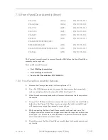
7.13
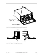
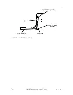
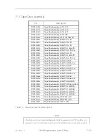
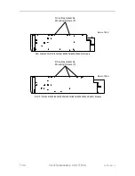
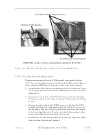
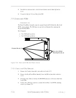
Drive Bay PCBA Assembly
RLS-4124
(8mm) P/N 501537-05-4
RLS-4221
(8mm) P/N 501537-01-3
RLS-44xx
(8mm) P/N 501537-02-1
RLS-5116
(SAIT) P/N 501537-04-7
RLS-5244
(SAIT) P/N 501537-03-9
RLS-62xx
(SDLT) P/N 501537-03-9
RLS-8116
(LTO) P/N 501537-04-7
RLS-8216H
(LTO) P/N 501537-01-3
RLS-8216C/8216CD/8236C/8236CD
(LTO) P/N 502117-02-1
RLS-8202/8204/8236/8244
(LTO) P/N 501537-03-9
RLS-8204D/8236D/8244D
(LTO) P/N 501957-01-3
RLS-8404/8444
(LTO) P/N 501537-02-1
RLS-8404D/8444D
(LTO) P/N 502117-01-3
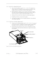
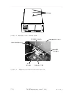
The Power Supply Module(s), all Tape Drives, all Drive Interface Adapters (DIAs),
the Sensor Master Assembly and the X-Clear Emitter PCBA must be removed from
the RLS before the drive bay PCBA can be replaced. No calibration is required after
replacing the Drive Bay PCBA FRU.
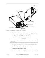
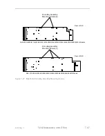
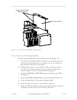
CAUTION
The pins of the four Channel (1-4) connectors on both sides of SCSI Drive Bay
PCBA Assemblies are easily bent while handling the board. If a bent pin is not
straightened perfectly before a Tape Drive or DIAs is installed, it is quite likely
that the pin will get permanently damaged during the insertion of the mating
connector.
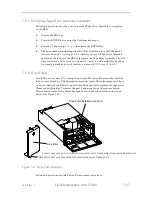
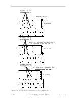
The DFA Drive Bay PCBA Assemblies (P/N 501957-01-3) only have connectors
with pins on the side that faces the Tape Drives, but equal care should be
given when handling. A bent pin that is not straightened perfectly before a
Tape Drive is installed is quite likely to get permanently damaged during the
insertion of the mating connector.
Summary of Contents for RLS-4470
Page 1: ...RLS 8000 Tape Library Technical Service Manual 501510 Rev S...
Page 2: ......
Page 14: ...xiv 501510 Rev S This page left blank intentionally...
Page 16: ...1 2 Introduction 501510 Rev S Table 1 1 Applicable Documents...
Page 20: ...1 6 Introduction 501510 Rev S This page left blank intentionally...
Page 23: ...501510 Rev S Description and Theory of Operation 2 3...
Page 34: ......
Page 50: ...3 16 The Operator Interface 501510 Rev S This page left blank intentionally...
Page 64: ...4 14 The Maintenance Menu 501510 Rev S This page left blank intentionally...
Page 65: ...501510 Rev S The Private Menu 5 1 5 The Private Menu...
Page 69: ...501510 Rev S The Private Menu 5 5 10 Close the Front Panel Door...
Page 188: ...8 10 Firmware Updating 501510 Rev S Figure 8 7 Properties Screen...
Page 205: ...501510 Rev S RLS Expansions 9 13 This page left blank intentionally...


