


501510 Rev. S
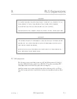
RLS Expansions
9-5
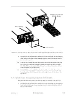
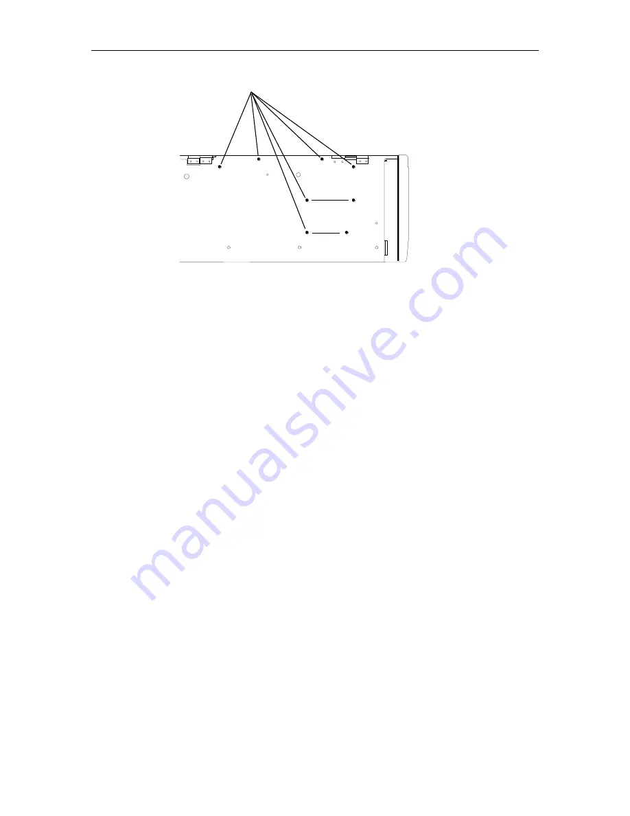
Interconnect PCBA Mounting Screws (8)
Front of RLS
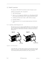
Figure 9-4 Interconnect PCBA Mounting Screws (Left Side)
8.
Remove the eight No. 1 Phillips screws that secure the Interconnect PCBA from
the left side of the chassis as shown in Figure 9-4.
9.
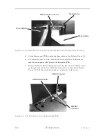
Lift the Interconnect PCBA up and out slightly to gain access to the cable con-
necting it to the Control Panel. Unplug the Control Panel cable and lift the In-
terconnect PCBA out of the chassis.
10.
Unplug the cable at the right end of the Sensor Slave Assembly as shown in Fig-
ure 7-38.
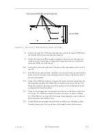
11.
If the RLS is not rack-mounted, carefully turn it on its left side (as seen from the
front) so that the Storage Array mounting screws located on the bottom of the li-
brary can be accessed.
12.
Using a No. 2 Phillips screwdriver, remove the lower or left two screws from the
chassis bottom that hold the Sensor Slave Assembly in place (see Figure 7-39).
Grasp the assembly before removing the top (last) screw and then gently pull it
out through the Front Panel/Door.
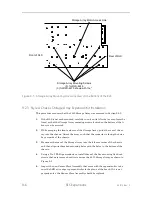
13.
There are five Storage Array mounting screws located on the bottom of the chas-
sis. Using a No. 2 Phillips screwdriver, remove the screws as shown in Figure
9-5. If the RLS is on its side, hold the Storage Array Assembly in place with one
hand while removing the final screw.
14.
Set the RLS chassis upright. Grasp the front and the rear of the Storage Array
Assembly and gently lift it up and then out through the front of the chassis.
Summary of Contents for RLS-4470
Page 1: ...RLS 8000 Tape Library Technical Service Manual 501510 Rev S...
Page 2: ......
Page 14: ...xiv 501510 Rev S This page left blank intentionally...
Page 16: ...1 2 Introduction 501510 Rev S Table 1 1 Applicable Documents...
Page 20: ...1 6 Introduction 501510 Rev S This page left blank intentionally...
Page 23: ...501510 Rev S Description and Theory of Operation 2 3...
Page 34: ......
Page 50: ...3 16 The Operator Interface 501510 Rev S This page left blank intentionally...
Page 64: ...4 14 The Maintenance Menu 501510 Rev S This page left blank intentionally...
Page 65: ...501510 Rev S The Private Menu 5 1 5 The Private Menu...
Page 69: ...501510 Rev S The Private Menu 5 5 10 Close the Front Panel Door...
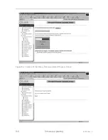
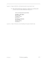
Page 188: ...8 10 Firmware Updating 501510 Rev S Figure 8 7 Properties Screen...
Page 205: ...501510 Rev S RLS Expansions 9 13 This page left blank intentionally...


