background image

A

Library Addresses

XLS Library Installation Manual


A-5

A.2

Addresses for Expansion Pod, I/O Ports, and Fixed Port 

Slots

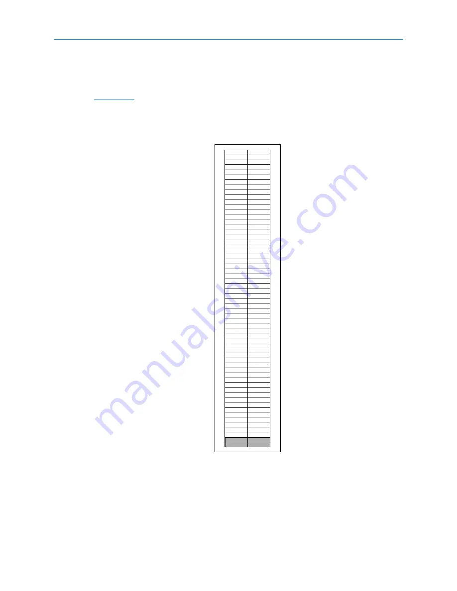
Figure A-4

 shows the physical addresses for the cartridge slots in an XLS-810160/810240 

expansion pod.

Figure A-4

Physical addresses for the slots in a XLS-810160/810240 expansion pod

Expansion Pod

A60
A59
A58
A57
A56
A55
A54
A53
A52
A51
A50
A49
A48
A47
A46
A45
A44
A43
A42
A41
A40
A39
A38
A37
A36
A35
A34
A33
A32
A31
A30
A29
A28
A27
A26
A25
A24
A23
A22
A21
A20
A19
A18
A17
A16
A15
A14
A13
A12
A11
A10
A09
A08
A07
A06
A05
A04
A03

B60
B59
B58
B57
B56
B55
B54
B53
B52
B51
B50
B49
B48
B47
B46
B45
B44
B43
B42
B41
B40
B39
B38
B37
B36
B35
B34
B33
B32
B31
B30
B29
B28
B27
B26
B25
B24
B23
B22
B21
B20
B19
B18
B17
B16
B15
B14
B13
B12
B11
B10
B09
B08
B07
B06
B05
B04
B03

Summary of Contents for XLS-810160

Page 1: ...XLS 810160 XLS 810240 Tape Libraries Installation Manual Document No 501801 Rev 07 01 19...

Page 2: ...keep the information contained in this document current and accurate as of the date of publication or revision However no guarantee is given or implied that the document is error free or that it is ac...

Page 3: ...to comply with FCC Rules Use shielded cables when connecting this device to others European Union Directive 89 336 EEC and Standard EN55022 Electromagnetic Compatibility This product has been tested a...

Page 4: ...oHS Restriction of the use of certain hazardous substances in electrical and electronic equipment in accordance with the European Directive The compliance date is July 1 2006 at which time Qualstar wi...

Page 5: ...erview 2 2 2 2 Installation Check List 2 4 3 Unpacking the XLS 3 1 3 1 Inspecting the Shipment 3 1 3 2 Unpacking the XLS 3 3 4 Installing the LRM 4 1 4 1 Extending the Leveling Feet 4 1 5 Installing a...

Page 6: ...1 9 Applying Power and Logging Into X Link 9 1 9 1 Preparing to Power on the Library 9 1 9 2 Connecting the Library to Power 9 3 9 3 Logging Into X Link 9 11 10 Configuring the Physical Library 10 1...

Page 7: ...g the Inventory and Locking the Doors 13 7 14 Testing the Installation 14 1 14 1 Putting the XLS in Logical Mode 14 1 14 2 Bringing a Logical Library Online 14 2 14 3 Starting the Application 14 3 14...

Page 8: ...Table of Contents viii 501801 Rev 07 01 19...

Page 9: ...00 and the XLS 810160 810240 This manual will focus on the XLS 810160 and XLS 810240 models Shown in Figure 1 1 on page 1 2 the library uses two building blocks The Library Resource Module LRM describ...

Page 10: ...1 1 About the XLS 1 2 501801 Rev 07 01 19 The XLS 85000 also referred to as a MEM2 contains 517 cartridges Figure 1 1 LRM with one MEM2...

Page 11: ...o 245 cartridges and up to two 10 slot I O ports As an option one Media Expansion Modules MEM can be installed on the left side of the XLS 810160 810240 See Section 1 3 on page 1 16 for more informati...

Page 12: ...controller see Section 1 2 1 on page 1 5 Touch screen and LEDs see Section 1 2 2 on page 1 8 Robotic handler and barcode reader see Section 1 2 3 on page 1 9 Tape drives see Section 1 2 4 on page 1 12...

Page 13: ...Figure 1 4 shows the location of the PC bay at the rear of the LRM The PC bay houses the system controller and slides in and out of the LRM for servicing Figure 1 4 Rear view of the LRM Power supplies...

Page 14: ...of a Linux based computer that controls the library The system controller Controls the operation of the distributed control boards DCBs Manages all communications between the XLS and the host applicat...

Page 15: ...anual XLS Library Installation Manual 1 7 Figure 1 6 System controller components in the PC bay Serial Ethernet connectors HBA connectors Host Bus Adapter cards Cooling fans EMI shield CAN bus control...

Page 16: ...r supply in the system controller and communicates with the system controller using a USB interface X Link Management Interface The X Link management interface can be accessed locally from the touch s...

Page 17: ...re also included on the back of each tape drive assembly and each power supply 1 2 3 Robotic Handler and Barcode Reader Shown in Figure 1 9 on page 1 10 the robotic tape handler within each LRM can ac...

Page 18: ...xis The Y axis is the vertical axis The Theta axis is the rotating axis that allows the gripper assembly to reach cartridge slots on the front back and sides of the cabinet The Z axis is the in and ou...

Page 19: ...ocedures are performed Inventory scan During an inventory scan the barcode reader scans each slot to determine which ones contain cartridges It also scans the barcode labels on the cartridges to estab...

Page 20: ...es include dual SCSI HD68 connectors and a single status LED while Fibre Channel tape drive assemblies include a duplex LC multi mode Fibre Channel receptacle and three LEDs Depending on the capabilit...

Page 21: ...lled from the rear of the LRM For safety reasons all tape drive or drive filler assemblies see Figure 1 13 must be installed in each drive bay in order for the library to operate If the library detect...

Page 22: ...rupting XLS operations Each I O port holds 10 cartridges in a removable magazine Depending on the model the XLS can include one or two I O ports For each I O port that is not installed the library inc...

Page 23: ...e XLS to precisely monitor all areas within the LRM and MEM cabinets as follows The beams of light at the rear of the cabinet can detect whether a cartridge is protruding from a slot If the door is cl...

Page 24: ...n store up to 517 cartridges The XLS 810160 810240 can be expanded by adding one XLS 85000 MEM to its left side A MEM derives its power and control from an attached LRM The carousel can rotate in eith...

Page 25: ...Into X Link Instructions for performing the initial power on and logging into X Link from the touch screen Chapter 10 Configuring the Physical Library Instructions for setting up the physical library...

Page 26: ...cks and places the cartridges Refer to the Glossary for the definitions of other specialized terminology 1 5 2 Typographic Conventions This manual uses the following typographic conventions For X Link...

Page 27: ...Notices and Notes Important notices and notes provide additional information and tips as described below Note Notes provide additional information related to the topic being discussed WARNING Personal...

Page 28: ...lanning Guide 501804 Information for preparing a site for XLS 810160 810240 installation XLS 810160 810240 Tape Library User s Guide 501803 Instructions for operating the XLS 810160 810240 XLS Library...

Page 29: ...rxls is the default name for the physical library See Figure 1 17 4 Press Enter The Download Manuals page opens as shown in Figure 1 18 Figure 1 17 Accessing the online manuals Internet Explorer shown...

Page 30: ...1801 Rev 07 01 19 5 Select the manual you are interested in Assuming that Adobe Acrobat or Acrobat Reader is installed on your system the PDF file opens See Figure 1 19 Figure 1 19 PDF file of example...

Page 31: ...XLS library contact an authorized reseller or Qualstar Technical Support Qualstar Corporation 1267 Flynn Road Camarillo CA 93012 Monday Friday 7 00 AM 4 00 PM PST Phone 805 416 7055 Toll Free 877 886...

Page 32: ...1 6 For More Information 1 24 501801 Rev 07 01 19...

Page 33: ...cessories you need to complete the installation Important Before starting the installation be sure that you have access to any planning diagrams or documents created when determining what XLS equipmen...

Page 34: ...tape drive assemblies Connect cables and terminators Connect to network or laptop Align gripper to MEM scan calibrate if installed Check hardware configuration Configure physical library Set target I...

Page 35: ...9 Applying Power and Logging Into X Link 8 Connect the library to a network or standalone computer align the gripper to the MEM if installed check the hardware configuration and configure the physica...

Page 36: ...be attached to the left side of an XLS 810160 or XLS 810240 Tape drive assemblies Qualstar The tape drives are installed in drive carriers at the factory Drive filler assemblies Qualstar All unused t...

Page 37: ...tion Note 040 XLS RLS and TLS Barcode Labels To obtain this document go to www qualstar com and click on the Support tab Pre printed barcode labels which are both human and machine readable are availa...

Page 38: ...hillips screwdriver Installer 5 32 inch Allen wrench Installer 1 4 inch Allen wrench Installer Wire cutters or scissors Installer Precision level Installer 3 16 inch hex wrench Installer For installin...

Page 39: ...Section 3 1 Unpacking the XLS see Section 3 2 on page 3 3 3 1 Inspecting the Shipment Before unpacking the cartons inspect the entire shipment as follows 1 Check the packing lists on each container to...

Page 40: ...g transport See Figure 3 1 3 Inspect the cartons and pallets for obvious damage for example punctures or water stains 4 Report any damage to the carrier Figure 3 1 Example Tip N Tell indicators Import...

Page 41: ...space to roll each unit off its pallet and into position Step Task Refer to 1 Remove the packaging Section 3 2 1 2 Remove the web straps Section 3 2 2 on page 3 5 3 Attach ramps to the pallet Section...

Page 42: ...the plastic sheeting surrounding the cardboard See Figure 3 2 3 Lift the cardboard cap off the top 4 Using a Phillips screwdriver remove the drywall screws that attach the cardboard to the pallet Figu...

Page 43: ...gure 3 3 6 Visually inspect the unpacked equipment for obvious shipping damage such as dented or scratched surfaces Report any damage to the carrier 3 2 2 Remove the Web Straps To remove the four web...

Page 44: ...e upper and lower eye bolts 4 Repeat steps 2 and 3 to remove the other straps 5 Remove the cardboard spacer from the top of the XLS 6 Using a 1 2 inch socket or open end wrench remove the four shippin...

Page 45: ...he pallet with four shipping restraints two on each side XLS 810160 or XLS 810240 To remove the back and front shipping restraints follow these steps 1 Locate the two shipping restraints at the back S...

Page 46: ...er the X axis 5 Remove the front right shipping restraint 6 For the left side shipping restraint an assitant will be needed Using wire cutters or scissors cut and remove the cable tie that holds the X...

Page 47: ...the help of an assistant and hold it aloft so the shipping restraint is visible as shown in figure Figure 3 9 9 Remove the shipping restraint 10 Carefully and slowly lower the X axis 11 Close the doo...

Page 48: ...of the MEM to the pallet There are two on either side See Figure 3 10 2 Using a 5 16 inch hex wrench included in the accessory box remove the shipping restraints from both sides Figure 3 10 Location o...

Page 49: ...allet follow these steps 1 Using a Phillips screwdriver remove the drywall screws securing the two ramps See Figure 3 11 2 Slide the ramps out from under the unit Figure 3 11 Location of ramps Importa...

Page 50: ...pallet Figure 3 12 LRM turned in the correct direction Important The pallet includes different sets of slots Be sure to use the correct slots for your equipment as follows XLS 810160 or XLS 810240 Use...

Page 51: ...n roll the unit into position Follow these steps 1 Confirm that all of the levelling feet are fully retracted See Figure 3 14 Figure 3 13 Attaching the ramps to the pallet XLS 810160 810240 shown CAUT...

Page 52: ...Save the packing materials in case any of the equipment needs to be moved or returned for service WARNING To avoid injury or equipment damage use three or more people when rolling the equipment to it...

Page 53: ...olves the following steps Extending the leveling feet see Section 4 1 4 1 Extending the Leveling Feet To extend the leveling feet follow these steps 1 Locate the four leveling feet on the base of the...

Page 54: ...re installing a MEM refer to Chapter 5 Installing a MEM or 7 If you are not installing a MEM turn all four jam nuts clockwise until they push up against the frame See Figure 4 3 Figure 4 2 Extending a...

Page 55: ...head screws shipped with the MEM Wire cutters or scissors 5 1 Preparing the LRM To prepare the LRM follow these steps Important For instructions for attaching a MEM after the LRM has been powered on...

Page 56: ...g a 2 Phillips screwdriver remove the two screws See Figure 5 1 3 Carefully slide the panel up until you can lift the hooks out of the corresponding slots on the frame See Figure 5 2 4 Set the screws...

Page 57: ...ncludes two inner and two outer hard stops which are simply 10 cap screws located at each end of the X axis See Figure 5 4 When the inner hard stops are installed the handler is prevented from traveli...

Page 58: ...axis 2 Using a 5 32 inch Allen wrench remove the appropriate inner hard stop from the X axis See Figure 5 5 5 3 Releasing the Carousel Locks in a XLS 85000 MEM To release the carousel locks follow th...

Page 59: ...and 4 as shown in Figure 5 6 3 Gradually remove screws 2 and 3 as follows a Loosen screw 2 a few turns b Loosen screw 3 a few turns c Repeat steps a and b until screws 2 and 3 can be removed from the...

Page 60: ...roller Cable The carousel controller cable connects the system controller in the LRM to the carousel controller at the back of the MEM This cable allows the LRM to provide power and control to the MEM...

Page 61: ...than the other six See Figure 5 8 2 Route the cable as follows Out the side of the LRM Into the side of the MEM Out the back of the MEM 3 Connect the cable to either of the two keyed connectors on the...

Page 62: ...align with the holes on the LRM 4 Push the MEM against the LRM and guide the bullet nose ends of the alignment pins into the corresponding holes on the LRM 5 Locate the three holes on the back of the...

Page 63: ...screws and washers 9 Insert the screws through their washers and into the holes 10 Tighten the screws with a 1 4 inch Allen wrench 5 6 Lowering the Leveling Feet To lower the leveling feet on the MEM...

Page 64: ...t steps 2 and 3 to extend the three other leveling feet 5 Check the alignment by placing a precision level on top of the LRM and MEM Figure 5 12 Loosening a leveling foot Figure 5 13 Extending a level...

Page 65: ...lace the panel next to the MEM and carefully lower it until the hooks on the panel engage with the corresponding slots on the MEM s frame 2 Insert the two screws in the holes at the bottom of the pane...

Page 66: ...EM 5 12 501801 Rev 07 01 19 5 After powering on the XLS log in and refer to the instructions in Section 10 2 Aligning the Gripper with a MEM on page 10 4 to align the gripper to the carousel slots and...

Page 67: ...nch included in the accessory box Wire cutters or scissors Important For instructions for attaching an expansion pod after the XLS 810160 810240 has been powered on and configured refer to the XLS Lib...

Page 68: ...screws 6 10 32 x 1 1 4 socket head screws 3 Left expansion pod 3 8 16 x 1 2 socket head screws 3 3 8 flat washers 3 6 1 Removing the Left Side Panel from the XLS 810160 810240 To remove the left side...

Page 69: ...e hooks out of the corresponding slots on the frame See Figure 6 2 4 Save the side panel and screws for future use if the expansion pod is removed from the LRM 6 2 Installing the Expansion Pod Mountin...

Page 70: ...the expansion pod locate the top and bottom hinge mounts the two alignment pins and the six flat head screws 4 Insert the narrow ends of the alignment pins into the corresponding holes on the top and...

Page 71: ...point upward See Figure 6 5 7 Hold the bottom hinge mount against the XLS 810160 810240 and route the expansion pod controller cable through the channel on the bottom hinge mount See Figure 6 6 Figur...

Page 72: ...inge pins See Figure 6 7 10 Attach the front L brace to the LRM as shown in Figure 6 8 Note that Use three 3 8 x 1 2 socket head screws and three 3 8 inch flat washers Install the screws from the insi...

Page 73: ...r to the left and right When an inner hard stop is removed the handler can reach into an attached expansion pod You need to remove the inner hard stop on the left side where you will install the expan...

Page 74: ...d stop from the X axis See Figure 6 10 6 4 Attaching the Expansion Pod to the XLS 810160 810240 To attach the expansion pod to the LRM follow these steps 1 If necessary lower the leveling feet on the...

Page 75: ...nge pins on the LRM into the corresponding holes on the pod See Figure 6 11 3 Connect the expansion pod controller cable to the keyed connector on the pod controller card See Figure 6 12 Figure 6 11 A...

Page 76: ...gure 6 13 5 Insert three 10 32 x 1 1 4 socket head screws through the three holes on the outside of the expansion pod See Figure 6 14 for the location of the top most hole 6 Using a 5 32 inch Allen wr...

Page 77: ...cation of the three top screws 2 Insert one screw in the hole at the bottom of the panel Using a 2 Phillips screwdriver tighten the screw 3 After installing the expansion pod power on the XLS as descr...

Page 78: ...6 5 Installing the Rear Side Panel 6 12 501801 Rev 07 01 19 Notes...

Page 79: ...ee Figure 7 1 To install a tape drive you simply slide the assembly into a drive bay and secure it with four screws CAUTION To avoid damaging the equipment and voiding your warranty do not attempt to...

Page 80: ...r safety and UL compliance a drive filler assembly see Figure 7 3 must be installed in any unused tape drive slot If there are empty tape drive slots the handler will be prevented from moving when pow...

Page 81: ...are controlled as follows Logical Library 1 contains one LTO3 SCSI tape drive The software application in the host computer communicates with the tape drive and the medium changer over a single SCSI b...

Page 82: ...SCSI tape drive The logical libraries are controlled as follows Logical Library 1 contains one LTO4 SCSI tape drive The software application in the host computer communicates with the tape drive and...

Page 83: ...ample Fibre Channel FC library that contains twelve tape drives and two Fibre Channel HBAs The XLS has been partitioned into three logical libraries as follows Logical Library 1 contains two tape driv...

Page 84: ...and tape drives across a switched fabric Figure 7 6 Example 3 Fibre Channel cabling diagram view from the back of the LRM Blank Drive Cover B C D A to FC switch Log Library 2 Log Lib 1 FC Log Lib 2 FC...

Page 85: ...hanger over two seperate SCSI buses The LTO4 SCSI tape drive carrier is self terinating and the other end is terminated by the host computer The lower port of HBA A in the system controller which prov...

Page 86: ...s view from the back of the LRM A B C D to FC switch Log Library 4 Log Lib 1 SCSI Log Lib 2 SCSI Log Lib 3 FC Log Lib 4 FC to FC switch Log Library 3 to SCSI host Log Library 2 to FC switch Log Librar...

Page 87: ...ports in the system controller and it controls the medium changer interface for the logical library Hosts 2 3 and 4 share access to the 10 tape drives but are not connected to the medium changer inter...

Page 88: ...which shows all 10 possible tape drive locations in an LRM Record the following information on the worksheet Drive type Enter the type of drive or n a for empty drive slots Interface Enter SCSI FC Fib...

Page 89: ...TO 3 Interface FC Serial No 1210075343 Log Lib 4 Bay position 2D Drive type LTO 3 Interface FC Serial No 1210074064 Log Lib 4 Bay position 1C Drive type LTO 3 Interface FC Serial No 1210075976 Log Lib...

Page 90: ..._ Log Lib _____________ Bay position 1D Drive type ___________ Interface ____________ Serial No ____________ Log Lib _____________ Bay position 2D Drive type ___________ Interface ____________ Serial...

Page 91: ...11 3 Push on the back of the tape drive to ensure that the connectors are fully seated and that the carrier s gasket has made a good seal against the drive bay 4 Using a Phillips screwdriver turn the...

Page 92: ...nstall drive filler assemblies shown in Figure 7 3 on page 7 2 in any unused positions CAUTION For safety and UL compliance a drive filler assembly must be installed in any unused tape drive slot If t...

Page 93: ...ibre Channel tape drive and HBA to the Fibre Channel switch The tape drives and the HBAs in the XLS both use multimode 62 5 125 fiber optic patch cables with duplex LC connectors For SCSI installation...

Page 94: ...oller 2 Set the shield aside 8 2 2 Connecting the Cables You can connect and control the medium changer and the tape drives in a number of ways using parallel SCSI buses Fibre Channel networks or a co...

Page 95: ...stem controller enumerates the SCSI HBAs first then the Fubre Channel HBAs See Figure 8 2 for examples Connecting SCSI Cables and Terminators To connect LTO3 tape drive SCSI cables and terminators fol...

Page 96: ...ect the HBA SCSI cables follow these steps 1 Connect the HBA as follows a Route an external SCSI cable through the appropriate slot on the back of the system controller b Attach the cable to a port on...

Page 97: ...e SCSI HBAs provide active termination Connecting Fibre Channel Cables To connect the Fibre Channel cables follow these steps 1 Connect one or more tape drives as follows a Use one hand to lift the sa...

Page 98: ...or switches 4 As an option the fibre channel cables attached to the tape drives may be attached to the three included cable routing brackets to route the cables downward If brackets are required to ro...

Page 99: ...8 2 3 Replace the EMI Shield After connecting the cables replace the EMI shield and tighten the three captive screws Figure 8 6 Securing the cables to the brackets Important Be careful to not damage t...

Page 100: ...8 2 Connecting the Cables 8 8 501801 Rev 07 01 19 Notes...

Page 101: ...w these steps 1 Make sure you have a power cord suitable for your input voltage and location see the XLS Library Product Specification 2 If you plan to connect the XLS to a UPS obtain the UPS and UPS...

Page 102: ...adequate to support the number of installed drive bays and an attached MEM 6 If a MEM is attached to the LRM confirm the following The carousel locks have been released See Section 5 3 on page 5 4 The...

Page 103: ...power input normally The unit switches to the second power input if the first has failed To power on a library with the standard power connection follow these steps 1 Locate the power switch and power...

Page 104: ...The battery module in the power PC bay provides enough backup power to safely shut down the XLS if an unexpected power failure occurs However the battery module does not provide enough power to prote...

Page 105: ...s attached loosen the captive screws and remove the restraint to access the power connectors 3 Connect one of the power cords to power inlet 1 on the left and then connect the second cord to power inl...

Page 106: ...e power switches to the on position See Figure 9 5 7 Wait for the power on processes to complete During power on The status LEDs on the front panel of the LRM flash intermittently The XLS scans the fi...

Page 107: ...f the library look at each power supply and confirm that the PWR Good LED is green and the Fault LED is off See Figure 9 8 on page 9 10 3 Rule out common explanations for a power on failure See Table...

Page 108: ...MEMs Carousel unable to move If you are using one or more MEMs and the carousel did not rotate confirm the following The carousel controller cable is attached correctly The carousel locks have been re...

Page 109: ...is blocked for example a cartridge may be protruding from a slot Solid yellow One or more I O ports is open Network Activity Flashing green There is activity on the Ethernet network currently not impl...

Page 110: ...and the tape drive is powered on Link Fibre Channel carrier only Off The tape drive is not connected to a Fibre Channel switch or a link is not established Green The tape drive is connected to an act...

Page 111: ...connected to one of the library s Ethernet ports and that it has been configured to access the library For instructions see Section 10 1 on page 10 1 LED state Meaning PWR Good Fault On green Off The...

Page 112: ...page The virtual keyboard opens as shown in Figure 9 10 Note that a stylus has been included with the accessory kit that can be used to control the touch screen Please be sure to only use the orange...

Page 113: ...re using the touch screen press Next on the virtual keyboard to display the Password field 4 Type your password in the Password field 5 If you are using the touch screen press Close on the virtual key...

Page 114: ...9 3 Logging Into X Link 9 14 501801 Rev 07 01 19 Notes...

Page 115: ...10 1 If a MEM or expansion pod is installed aligning the gripper to the extra slots See Section 10 2 on page 10 4 Verifying the hardware configuration See Section 10 4 on page 10 19 Entering basic in...

Page 116: ...ions with a laptop or other standalone computer Required tools and equipment Make sure you have the following A standalone or networked computer running one of the following Internet browsers Microsof...

Page 117: ...tarxls in the address line for the browser See Figure 10 2 6 Press Enter The X Link log in page is displayed 7 Log into X Link as described in Section 9 3 on page 9 11 Important The XLS uses cookies t...

Page 118: ...e 10 3 6 Press Enter The X Link log in page opens 7 Log into X Link as described in Section 9 3 on page 9 11 10 2 Aligning the Gripper with a MEM If you have attached a MEM to the LRM you must align t...

Page 119: ...rom X Link press the Home button in the upper right corner of any page to return to the Home page 3 Select Service View to display the Service portlet shown in Figure 10 5 4 From the Change Configurat...

Page 120: ...creen appears see Figure 10 6 enter the approproate password and select Save Changes If the password is not known or after entering the password it does not allow the Hardware Configuration page to op...

Page 121: ...an easily accessible location 7 Open all doors 10 2 2 MEM Alignment To align the gripper to a MEM follow these steps 1 Insert the gripper alignment cartridge into slot 36 of the carousel use whicheve...

Page 122: ...ent cartridge 6 Remove the gripper alignment cartridge 10 2 3 Updating the Alignment after MEM Calibration To update the gripper alignment after obtaining the Theta Position and X Position values foll...

Page 123: ...XLS updates the gripper alignment so it can access the new slots 10 3 Calibrating an Expansion Pod Equipped Library If you have attached a pods to the LRM you must calibrate the pod to ensure that the...

Page 124: ...3 Expansion pod columns are designated A as the front column the column closest to the front of the library and B as the rear column See Figure 10 10 4 Make sure the XLS tape library has firmware Vers...

Page 125: ...tion cartridges should be installed in the TOP MOST slot slot 60 and the FIFTH slot from the bottom NOT the bottom most slot 6 Make sure the pod calibration cartridges are pushed all the way back into...

Page 126: ...nch to remove the cap screw See Figure 10 12 8 Make sure the LRM door is open 9 Power on the XLS Tape Library 10 Login to the X link Interface using the Administrator account and password Figure 10 12...

Page 127: ...are Configuration The Hardware Configuration page opens as shown in Figure 10 15 on page 10 14 13 If the Enter Service Password screen appears see Figure 10 14 enter the approproate password and selec...

Page 128: ...wn by hand slowly until the gripper is level with slot 25 17 Make sure the Gripper Alignment Cartridge indicates THIS SIDE UP FOR THETA ALIGNMENT or with BASE facing upward 10 3 2 For the Expansion Po...

Page 129: ...is aligned with the gripper assembly guide rod Please verify this alignment using a flashlight You may need to adjust the gripper alignment cartridge up and down to insure that it is properly seated...

Page 130: ...n B B 30 11 Repeat the above steps 2 through 8 with the Gripper Alignment Cartridge for Column B 10 3 3 Find the Average X and Theta Values 1 Add the X position values for each column and find the ave...

Page 131: ...Physical Library XLS Library Installation Manual 10 17 10 3 4 Hardware Configuration 1 From the X link home page select ServiceView to display the Service portlet as shown in Figure 10 17 Figure 10 1...

Page 132: ...10 18 3 Under the Carousels Pods section select Pod2 from the appropriate drop down list Carousel Pod installed on left 4 Input the average Theta position yaw values as recorded above into the Theta A...

Page 133: ...rdware Configuration When it manufactures the XLS to your specifications Qualstar creates a unique hardware database describing the configuration of the library The XLS uses the information in this da...

Page 134: ...n in the upper right corner of any page to return to the Home page 2 From the Home page select Service View to display the Service portlet shown in Figure 10 20 3 From the Change Configuration section...

Page 135: ...e and drive bays are shown in their correct positions 5 In the Doors section of the page review the information displayed for the door Make sure the correct information is displayed 6 In the I O Ports...

Page 136: ...a network and logging in you can enter basic configuration information for the library including the following Network address see Section 10 5 2 on page 10 23 Contact names and addresses see Section...

Page 137: ...library host name and the IP address To view or edit the network configuration follow these steps 1 Access the Configuration portlet as described in Section 10 5 1 on page 10 22 Figure 10 22 Configur...

Page 138: ...e dynamic domain name system DNS on your network to make the library name available to the network 4 As required enter information for the IP Address Subnet Mask and Default Gateway fields 5 As multic...

Page 139: ...as described in Section 10 5 1 on page 10 22 2 Select View Edit Contact Information The View Edit Contact Information page opens as shown in Figure 10 24 3 View or edit the contact information for the...

Page 140: ...ge 10 22 2 Select View Edit Administrator Information The View Edit Administrator Information page opens as shown in Figure 10 25 3 View or edit the administrator information for the library Required...

Page 141: ...press the Home button in the upper right corner of any page to return to the Home page 2 Select Administrator View to display the Users Groups portlet shown in Figure 10 26 3 From the Users Groups por...

Page 142: ...as shown in Figure 10 27 7 Enter and re enter the new password Passwords Are case sensitive Must contain between 6 and 32 characters May contain alphabetic or numeric characters 8 Press Save Changes...

Page 143: ...utton in the upper right corner of any page to return to the Home page Important Before changing the default target IDs review any requirements for the software application Figure 10 28 Default target...

Page 144: ...elect Administrator View or Show All to display the Configuration portlet shown in Figure 10 29 3 Select View Edit HBA Target ID The View Edit HBA Target ID page opens as shown in Figure 10 30 Figure...

Page 145: ...st select a new target ID for the HBA port 6 Press Save HBA Target ID to save the information The new target ID takes effect as soon as the confirmation page appears Editing Tape Drive Target IDs With...

Page 146: ...ay where 1 is the rightmost position and 2 is the leftmost position when the library is viewed from the back c From the Row drop down list select the location of the drive bay where A is the bottom dr...

Page 147: ...the following which are available from the Settings Policies portlet E mail settings see Section 10 6 2 on page 10 34 SNMP settings see Section 10 6 3 on page 10 36 Event log settings see Section 10...

Page 148: ...e Settings Policies portlet as described in Section 10 6 1 on page 10 33 2 Select View Edit E mail Settings The View Edit E mail Settings page opens as shown in Figure 10 34 Important After configurin...

Page 149: ...hat a test message from the sender specified in the Sender Name field arrived in the test e mail account s mailbox In some cases you may have to wait a few minutes to receive the test message 5 Press...

Page 150: ...Section 10 6 1 on page 10 33 2 Select View Edit SNMP Settings The View Edit SNMP Settings page opens as shown in Figure 10 35 3 Enter a name for the SNMP community in the Community Name field 4 Press...

Page 151: ...events As soon as there are more events in the log than this number the library deletes the oldest event 4 In the Save events for field enter the number of hours days or weeks to save events for Then...

Page 152: ...eck field specify how often you want the library to send reminders to check the air filters The default is 120 days however you may want to adjust this time to ensure optimum read and write reliabilit...

Page 153: ...ts to specified recipients when events of this severity level or above occur See Figure 10 38 6 From the Event Severity to Page drop down list select a severity level The XLS sends pager alerts to spe...

Page 154: ...10 6 Defining Other Library Settings and Policies 10 40 501801 Rev 07 01 19 Notes...

Page 155: ...medium changer interface on a first come first served basis Figure 11 1 on page 11 2 depicts an example XLS configuration that shows the high level relationship between the physical library the logica...

Page 156: ...ysical library logical libraries and software applications Physical Library System Controller Medium Changer Interface and Robotics I O Port I O Port Host Computer 2 Software Application 2 Host Comput...

Page 157: ...ate a new logical library 11 2 1 Accessing Logical Library Information To access information about logical libraries follow these steps 1 If necessary press the Home button in the upper right corner o...

Page 158: ...It cannot contain blanks 2 The operating mode for the logical library for software compatibility 3 Whether barcode labels are required on every cartridge and whether the labels must contain checksum...

Page 159: ...l need to edit the logical library definitions later on As you create the worksheet refer to the explanations in Section 11 2 3 on page 11 6 to learn the possible values for each option Option Total A...

Page 160: ...w many XLS resources are unassigned cartridge slots tape drives and I O ports You can select from these resources when you define the new logical library 3 From the Administration list select Create a...

Page 161: ...red in this logical library The default setting is yes option box checked If you clear the Barcode labels required option the XLS allows both labeled and unlabeled cartridges in the logical library d...

Page 162: ...smaller than the number of available slots h In the Number of I O Ports field indicate how many I O ports if any you want to allocate to this logical library A logical library can have zero to two I...

Page 163: ...logical library When you press Next Step the second Create Logical Library page opens as shown in Figure 11 5 6 Enter the name and user ID of the person who is to administer the new logical library 7...

Page 164: ...division that owns any data stored on the logical library 9 Press Finish to create a logical library with the requested number of cartridge slots tape drives and I O ports Figure 11 6 Create Logical...

Page 165: ...a logical library follow these steps 1 Access the Logical Libraries portlet as described in Section 11 2 1 on page 11 3 2 Select the radio button to the left of the logical library name then select V...

Page 166: ...updates when the drop down lists are changed 6 To export the inventory report press Excel XML or CSV Then as prompted save the file 7 Print the report s to use when installing cartridges Table 11 2 de...

Page 167: ...a cartridge 5 The element is empty Bar Code If the element contains a cartridge the identifier on its barcode label Action Lists a variety of operations that can be performed for a particular slot de...

Page 168: ...11 3 Viewing the Inventory Report 11 14 501801 Rev 07 01 19 Notes...

Page 169: ...ata and cleaning cartridges see Section 12 4 on page 12 5 12 1 Installing Cartridges in the Reserved Slots Each LRM includes five reserved slots for the tape drive calibration cartridge and four clean...

Page 170: ...quested from X Link They are not intended for day to day tape drive cleaning operations and are installed in locations that are inaccessible to the software applications Procedure To install cartridge...

Page 171: ...s Keep cartridges in their protective plastic cases or in a covered magazine when handling them outside the XLS Figure 12 2 Installing the calibration cartridge Important To ensure that the tape drive...

Page 172: ...adhesive labels to the cartridge anywhere except in the recess provided on the front Labels applied elsewhere could cause the cartridge to become jammed inside a tape drive or magazine Use only ink w...

Page 173: ...des 116 cartridge slots Carousels The carousel in an XLS 810160 provides storage slots for 155 cartridges while a XLS 810240 has 235 storage slots Fixed port assemblies If fewer than two I O ports are...

Page 174: ...4 Ensure that the write protect switches are to the left then insert the cartridges into the slots 5 As required install cleaning cartridges for each logical library partition Refer to the software d...

Page 175: ...se steps 1 Open the door on the XLS 2 Check the cartridge slots to ensure that all cartridges are fully inserted in the slots and that none of the tapes are protruding 3 Check the tape drives to ensur...

Page 176: ...stored in slot A50 into each tape drive to precisely locate the tape drive s position To scan and calibrate the fiducials follow these steps 1 If necessary apply power to the library and log in to X L...

Page 177: ...e Configuration The Hardware Configuration page opens as shown in Figure 13 4 on page 13 4 5 If the Enter Service Password screen appears see Figure 13 3 enter the approproate password and select Save...

Page 178: ...From the Fiducials section of the page select Home Robot to home the robot on all axes 8 Select I O Ports from the Fiducials section of the page to scan the fiducials on the I O ports Then wait while...

Page 179: ...ibration has completed select Dump Database from the Fiducials section of the page The results page indicates which if any fiducials remain unscanned See Figure 13 5 12 If any of the fiducials display...

Page 180: ...Wait while the handler scans the barcode label on each cartridge then select Sync Inventory to update the logical library inventories with the results of the physical library scan 4 From the Misc sec...

Page 181: ...allation Manual 13 7 6 Refer to Section 11 3 Viewing the Inventory Report on page 11 11 to generate a new report of cartridges for each logical library You can compare this report to the previous one...

Page 182: ...13 3 Scanning the Inventory and Locking the Doors 13 8 501801 Rev 07 01 19 Notes...

Page 183: ...tting the XLS in logical mode in preparation for bringing the logical libraries online In logical mode one or more software applications control the library and you interact with X Link from a logical...

Page 184: ...event is logged in the event log and a message is sent to designated users All other logical libraries and the tape drives remain in their current states To bring a logical library online follow these...

Page 185: ...e 14 2 4 Press Yes to confirm that you want to bring the library online 14 3 Starting the Application After bringing the logical library online start the backup software application and verify the fol...

Page 186: ...to the HBA port you specified when completing the Create Logical Library wizard See Section 11 2 on page 11 3 Correct Port IDs and LUNs Make sure the port IDs and logical unit numbers LUNs are define...

Page 187: ...stem controller fails or if you want to return to your initial configuration See the XLS Technical Service Manual for instructions To download a copy of the configuration file follow these steps 1 If...

Page 188: ...501801 Rev 07 01 19 3 From the Configuration portlet select Manage Configurations The Manage Configurations page opens as shown in Figure 14 4 indicating which configuration files are ready to be dow...

Page 189: ...own in Figure 14 5 opens allowing you to save or open the configuration file xls_0910244_Auto_A tar gz 5 Press Save A window similar to the one in Figure 14 6 opens allowing you to specify a destinati...

Page 190: ...downloaded the configuration file press Done to return to the Home page 8 Make a backup copy of the downloaded file and save it in a secure location Important Refer to the XLS Library Technical Servi...

Page 191: ...are assigned when the logical libraries are created To determine the physical address for a particular cartridge slot or tape drive within the physical library refer to the figures listed in Table A 1...

Page 192: ...d address for each tape drive position as viewed from the front Note Slot A50 in the carousel is reserved for the calibration cartridge and slots A46 A49 are reserved for the cleaning cartridges used...

Page 193: ...the fixed address for each tape drive position as viewed from the front Figure A 2 Physical addresses for the carousel of the XLS 810240 and 5 drive bays installed in positions 1A 2E view from the fro...

Page 194: ...Rev 07 01 19 Figure A 3 shows the physical addresses of the tape drives in the XLS 810160 810240 as viewed from the back Figure A 3 Physical addresses for the tape drives in the XLS 810160 810240 as...

Page 195: ...pansion pod Expansion Pod A60 A59 A58 A57 A56 A55 A54 A53 A52 A51 A50 A49 A48 A47 A46 A45 A44 A43 A42 A41 A40 A39 A38 A37 A36 A35 A34 A33 A32 A31 A30 A29 A28 A27 A26 A25 A24 A23 A22 A21 A20 A19 A18 A1...

Page 196: ...gure A 6 shows the physical addresses for the 10 fixed port slots The XLS 810160 810240 always has one I O port on the right Figure A 5 Physical addresses for the I O port slots if installed view from...

Page 197: ...dresses for the cartridge slots on the carousel in the Media Expansion Module MEM The five slots A46 A50 are reserved for pass through Figure A 7 Physical addresses for the slots in an XLS 85000 Media...

Page 198: ...A 3 Addresses for the Media Expansion Module MEM A 8 501801 Rev 07 01 19 Notes...

Page 199: ...a cartridge A cartridge slot is referred to as a storage element in the SCSI standard drive bay The removable hardware in the library that can contain up to two tape drives drive carrier The hardware...

Page 200: ...ted by the library have two ports which means you can connect two networks or SCSI buses to each card hot swappable A library component such as tape drive assemblies fans and power supplies that can b...

Page 201: ...responds to SCSI commands sent by initiators or host applications and sends instructions to the system controller to move cartridges between tape drives cartridge slots and I O ports MEM Media Expans...

Page 202: ...Management Protocol stylus A pen shaped instrument that can be used when inputting data or accessing menus on the libraries touch screen display system controller The PC within the library that manag...

Page 203: ...ng SCSI 8 3 EMI shield 8 2 Ethernet 10 3 Fibre Channel 8 5 calibration defined 1 11 calibration cartridge defined GL 1 installing 12 1 location A 2 when used 1 11 carousel addresses A 5 A 7 defined GL...

Page 204: ...eleting 10 36 event log settings 10 36 Event Severity to Email field 10 39 Event Severity to Page field 10 39 Excel exporting data to 11 12 exporting XLS information 11 12 F Fault LED 9 9 9 11 Fibre C...

Page 205: ...eatures 1 4 defined GL 2 described 1 4 LEDs 9 9 light curtain 1 15 defined GL 2 Link LED 9 10 logging out policy for idle users 10 37 logical library administrator 11 9 assigning resources 11 8 bringi...

Page 206: ...stalling cartridges 12 1 Robot Activity LED 9 9 robotics GL 4 S safety notices 1 19 saving configuration 14 5 SCSI connecting cables and terminators 8 3 defined GL 4 example cabling diagram 7 3 7 4 7...

Page 207: ...problems 14 4 typographic conventions 1 18 U unpacking instructions 3 3 user logging off when idle 10 37 user group defined GL 4 user ID default system administrator 9 13 V virtual keyboard 9 12 GL 4...

Page 208: ...Index IN 6 501801 Rev 07 01 19...

Reviews: