2
About the XLS
XLS Library Technical Service Manual
2-25
Tape Drive Assemblies
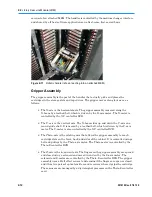
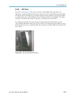
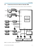
Shown in
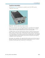
Figure 2-13
, an XLS tape drive assembly consists of an LTO tape drive
enclosed in a drive carrier.
Figure 2-13
Fibre Channel tape drive assembly (rear view)
Two models of tape drives are available: SCSI tape drive assemblies include dual SCSI
HD68 connectors and a single status LED, while Fibre Channel tape drive assemblies
include a duplex LC multi-mode Fibre Channel receptacle and three LEDs.
In addition to the connectors, each drive carrier includes a cooling fan, the drive carrier
DCB, and a DC-to-DC power supply. A digital signal processor provides communication
between the library and the tape dri
ve’
s serial port for configuring the drive and obtaining
status. The serial port is not used to read or write data to the tape. The drive carrier DCB
communicates with the system controller using the CAN1 bus. The DC power supply is
controlled by the drive bay processor.
Depending on the capabilities of the application software being used, the Fibre Channel
tape drive assemblies can be removed and replaced without powering down the library.
The library automatically detects the presence of a new tape drive.
Summary of Contents for XLS Series
Page 1: ...Technical Service Manual Document No 501610 Rev 07 01 19 XLS Series of Tape Libraries...
Page 14: ...501610 Rev 07 01 19 Part I Before You Begin Notes...
Page 58: ...3 7 Cabling for the Carousel Controller 3 12 501610 Rev 07 01 19 Notes...
Page 70: ...4 5 Inspecting and Cleaning the Gripper and Barcode Reader 4 12 501610 Rev 07 01 19 Notes...
Page 72: ...Part II Using X Link 501610 Rev 07 01 19 Notes...
Page 96: ...Part III Replacing FRUs 501610 Rev 07 01 19 Notes...
Page 136: ...8 8 Bringing a Tape Drive Online 8 14 501610 Rev 07 01 19 Notes...
Page 158: ...9 5 Replacing a Drive Bay with a Cartridge Bay 9 22 501610 Rev 07 01 19 Notes...
Page 172: ...10 3 Replacing a Side Panel 10 14 501610 Rev 07 01 19 Notes...
Page 186: ...11 3 Upgrading a Fixed Port Assembly to an I O Port 11 14 501610 Rev 07 01 19 Notes...
Page 226: ...12 6 Replacing the Y Motor Assembly 12 40 501610 Rev 07 01 19 Notes...
Page 324: ...Part IV Reference 501610 Rev 07 01 19 Notes...
Page 352: ...B 2 Packing the XLS B 14 501610 Rev 07 01 19 Notes...
Page 354: ...C 2 501610 Rev 07 01 19 Notes...


