MITX-V1K0 Series - User Guide, Rev. 1.0
// 64
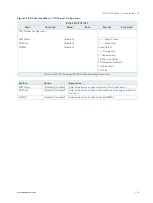
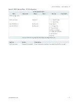
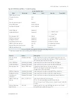
Table 47: Pin Assignment JP6
Jumper Position
Description
Pin 1-2
Pin 2-3
X
-
Normal operation (default position)
-
X
Enable Clear CMOS RTC content
(board does not boot with the jumper in this position)
“
X” = Jumper set (short) and “-” = jumper not set (open)
Do not leave the jumper in position 2-3, otherwise if the power is disconnected, the
battery will fully deplete within a few weeks.
7.20.5.
Backlight Power Enable Selection for LVDS1 (JP7)
The jumper JP7 can be used to select voltage level of backlight enable signal for LVDS1.
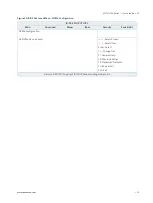
Figure 42: Backlight Enable Selection JP7
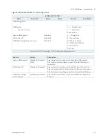
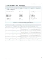
Table 48: Pin Assignment JP7
Jumper 1 Position
Description
Pin 1-3
Pin 3-5
X
-
Backlight Enable Level = +3.3 V
-
X
Backlight Enable Level = +5 V
Jumper 2 Position
Description
Pin 2-4
Pin 4-6
X
-
Backlight Enable High Active
-
X
Backlight Enable Low Active
“
X” = Jumper set (short) and “-” = jumper not set (open)
2
3
1
2
1
6
5


