MITX-V1K0 Series - User Guide, Rev. 1.0
// 63
7.20.2.
AT / ATX Power Mode Selection (JP3)
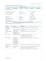
The jumper JP3 can be used to select AT power mode or ATX power mode.
Figure 39: AT / ATX Power Mode Selection JP4
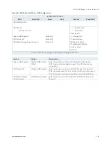
Table 45: Pin Assignment JP4
Jumper Position
Description
Pin 1-2
Pin 2-3
X
-
ATX Mode
-
X
AT Mode
“
X” = Jumper set (short) and “-” = jumper not set (open)
7.20.3.
USB Power Selection (JP4)
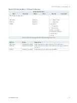
The "USB Power Selection" jumper (JP4) can be used to determine whether the USB ports are powered in the S4 / S5
state.
Figure 40: USB Power Selection JP4
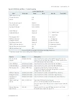
Table 46: Pin Assignment JP4
Jumper Position
Description
Pin 1-2
Pin 2-3
X
-
USB power will be cut off in S4 & S5 state
-
X
USB power is always supplied
“
X” = Jumper set (short) and “-” = jumper not set (open)
7.20.4.
Clear CMOS Selection (JP6)
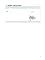
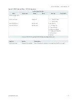
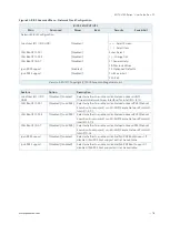
The jumper JP6 can be used to clear CMOS RTC content.
The jumper has two positions: Pin 1-2 mounted is the default configuration.
Figure 41: Clear CMOS Selection JP6
2
3
1
2
3
1


