NWA-6500 Series - User Guide, Rev. 1.4
// 21
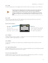
Table 1: Speed LED Status
LED Status
Description
Red LED On
1000 Mbit/s link established
Green LED On
100 Mbit/s link established
LED Off
10 Mbit/s link established
4.2.5.
LAN Bypass LED
The LAN bypass LED lights up yellow when a pair of LAN ports is operating in bypass mode. The LED "Bypass1" is for
the pair of LAN3 & LAN4 while the LED "Bypass2" for the pair of LAN5 & LAN6.
4.2.6.
Status LED
The status LED lights up green when the output value of the port GP10 from Super I/O is high.
4.2.7.
Alarm LED
The alarm LED lights up red when the output value of the port GP11 from Super I/O is high.
4.2.8.
Wireless LED
The wireless LED blinks green when the data is transferring over the WLAN card or 3G / 4G card.
4.2.9.
User-defined LED
The user-defined LED "UD1" and "UD2" light up green when the output value of the port GP12 and GP13 from Super I/O
is high respectively.
4.2.10.
Programmable Switch Button
The programmable switch button allows to activate one of three different functions. The function of the switch
button can be selected in BIOS setup.
Table 2: Functions of Programmable Switch Button
Function
Action
Description
Power Switch
Push On
Power on / off the system
Reset Switch
Push On
Reset the system
GPI Switch
Normal
Input High to the port GP20 of Super I/O
Push On
Input Low to the port GP20 of Super I/O

