background image

Chapter 1 

16 

QDSP-207B User’s Manual 


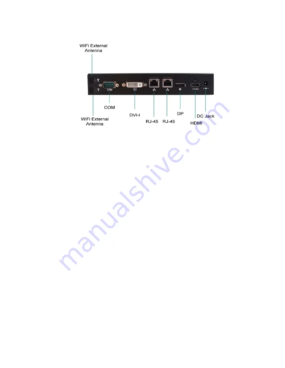
Rear I/Os 


Figure 2 Rear I/Os 

DC Jack 

The supplied power adapter converts AC power to DC for use with this jack. 
Power supplied through this jack supplies power to the PC. To prevent damage 
to the PC, always use the supplied power adapter. 


HDMI 

HDMI connector for display output   


DP 

Display Port   


Ethernet 

The eight-pin RJ-45 LAN port supports a standard Ethernet cable for 
connection to a local network. 


DVI-I  

DVI-I connector for DVI-D or VGA output   


COM 

D-Sub 9 pin connector for RS-232 connection   


WiFi External Antenna   

Spared hole on the casing for connecting WiFi external antenna   

Summary of Contents for QDSP-207B

Page 1: ...I QDSP 207B User s Manual QDSP 207B Digital Signage Player with Intel Ivy Bridge Platform User s Guide...

Page 2: ...tory Compliance Statements 8 Maintaining Your Computer 9 Chapter 1 Introduction 12 Overview 12 Product Specifications 13 System tour 14 Mechanical Dimensions 17 Chapter 2 Getting Started 18 Setting up...

Page 3: ...Ie Installation 27 Table 1 QDSP 207B product specifications 13 Table 2 BIOS Main Menu 29 Table 3 Advanced Menu 30 Table 4 Advanced Menu Display Configuration 31 Table 5 Advanced Menu Power Management...

Page 4: ...Figures Tables 4 QDSP 207B User s Manual Table 17 Boot Menu 41 Table 18 Security Menu 42 Table 19 Save Exit Menu 43...

Page 5: ...installation instructions in this user s guide for precautions and procedures If you have any questions please contact our Post Sales Technical Support Access can only be gained by service persons or...

Page 6: ...aligned to avoid bending any connector pins Also before connecting a cable make sure both connectors are correctly oriented and aligned CAUTION Do not attempt to service the system yourself except as...

Page 7: ...t handle or store system boards near strong electrostatic electromagnetic magnetic or radioactive fields Instructions for Lithium Battery WARNING Danger of explosion w hen battery is replaced w ith in...

Page 8: ...ices FCC Compliance Statement This equipment has been tested and found to comply with limits for a Class Adigital device pursuant to Part 15 of the FCC rules These limits are designed to provide reaso...

Page 9: ...ised Consideration should be given to the maximum rated ambient temperature Overheating can cause a variety of problems including premature aging and failure of chips or mechanical failure of devices...

Page 10: ...with the cost of the device Surge protectors prevent voltage spikes from entering a system through the AC power cord Surge protectors however do not offer protection against brownouts which occur whe...

Page 11: ...eriod of time when AC power is lost UPS systems that provide only 5 minutes of battery power let you conduct an orderly shutdown of the system but are not intended to provide continued operation Surge...

Page 12: ...07B provides high reliability for harsh environments compactsize high performance and is highly suited to a wide range of industrial applications such as Digital Signage Gaming Transportation Surveill...

Page 13: ...Fi status LED 1x 3G external antenna Rear IO 1x DC JACK 1x DVI I for DVI D or VGA output 1x HDMI 1x DP 2x RJ 45 GbE ports 1x COM Port support RS 232 422 485 2x WiFi external antenna Expansion Slot 2 x...

Page 14: ...ering ON and OFF the system Clear CMOS Button To clear the CMOS use the tip of a pen to press the button briefly for less than three seconds WiFi LED Green The WiFi LED will light when the WiFi is on...

Page 15: ...l Antenna Spared hole on the casing for connecting 3G external antenna Phone Jack Audio Out The stereo headphone jack is used to connect the system s audio outsignal to amplified speakers or headphone...

Page 16: ...To prevent damage to the PC always use the supplied power adapter HDMI HDMI connector for display output DP Display Port Ethernet The eight pin RJ 45 LAN port supports a standard Ethernet cable for co...

Page 17: ...Chapter 1 17 QDSP 207B User s Manual Mechanical Dimensions 200 x 35 x 153 1 mm W x H x D Figure 3 Mechanical Dimensions...

Page 18: ...ect the DVI Connect the DV I cable from your display to the DV I port Figure 4 Connect the DVI cable NOTE When the system reboots without connecting the DVI there might be no image on screen when you...

Page 19: ...ome with a keyboard and mouse but you can use any USB keyboard or mouse with your computer Figure 5 Connect USB mouse keyboard NOTE Using a third party USB mouse or keyboard may require software drive...

Page 20: ...t with the pin definitions Pin RS 232 RS 422 Half Duplex RS 485 Full Duplex RS 485 1 DCD TX DATA TX 2 RXD RX NA RX 3 TXD TX DATA TX 4 DTR RX NA RX 5 GND GND GND GND 6 DSR NA NA NA 7 RTS NA NA NA 8 CTS...

Page 21: ...er 2 21 QDSP 207B User s Manual Connecting to a network device Connect one end of a network cable to the LAN port on the system rear panel and the other end to a hub or switch Figure 7 RJ45 connector...

Page 22: ...the system 1 Connect the supplied AC power cord to the system AC power inlet 2 Connect the other end of the AC power cord to a corresponding outlet 3 Press the power switch to turn on the system Figu...

Page 23: ...ke out the VESAmounting kit form your package and facing it onto the bottom of QDSP 207B then tightening the screws on your QDSP 207B as figures shown below Figure 9 VESA Mount Assembly 2 Following fi...

Page 24: ...condly place the QDSP 207B on the VESAmounting kit and then tightening the screws from the holes on both sides of the VESA bracket make sure the computer is fitting well on the bracket Figure 11 VESA...

Page 25: ...oosening the two screws on the bottom of QDSP 207B as shown below Figure 12 Opening the Cover on the Bottom Then you may able to change the DDR SO DIMM and or mini PCIe modules Figure 13 Bottom view o...

Page 26: ...degree angle into the socket Figure 14 SO DIMM Installation 1 Align the SO DIMM Memory Module with the onboard socket 4 Fully insert the module into the socket until a click is heard 5 Press down on t...

Page 27: ...27 QDSP 207B User s Manual Changing mini PCIe 1 Place your mini PCIe module toward the mini PCIe socket Figure 16 Mini PCIe Installation 2 Tightening the screw on the hole of the mini PCIe module as s...

Page 28: ...se contact us AMI s ROM BIOS provides a built in Setup program which allows the user to modify the basic system configuration and hardware parameters The modified data will be stored in a battery back...

Page 29: ...eens Table 2 BIOS Main Menu BIOS SETUP UTILITY M a i n A d v a n c e d B o o t S e c u r i t y S a v e E x i t Product Information Select Screen Select Item Enter Sel ect Change Opt F1 General H elp F...

Page 30: ...2 Boot Disabled Audio Controller Enabled DisplayC onfiguration Power Management Configuration CPU Advanced Configuration Trusted Computing SATA Configuration Intel R Rapid Start Technolog y Intel TXT...

Page 31: ...elp F2 Previous Val ues F3 Optimized Defaults F4 Save Exit ESC Exit Aperture Size 256 MB DVMT Pre Allocated 64M DVMT Total Gfx Mem 256 M IGFX Boot Type VBIOS Default Version 2 15 1227 Copyright C 2010...

Page 32: ...end to RAM Restore AC Power Loss Power Off Resume By PCIE D evice Disabled Resume By RTC Alarm Disabled EUP Power Savi ng Mode Disabled Watchdog Timer Configurati on Version 2 15 1227 Copyright C 2010...

Page 33: ...Mode Enabled Hyper Treadi ng Enabled VT d Enabled Active Processor Cor es All Limit CPUID Maxi mum Disabled Execute Disable Bit Intel Virtualization Tech Enabled Disabled Version 2 15 1227 Copyright C...

Page 34: ...a v e E x i t Configuration Select Screen Select Item Enter Sel ect Change Opt F1 General H elp F2 Previous Val ues F3 Optimized Defaults F4 Save Exit ESC Exit SecurityDevice Support Disable Current...

Page 35: ...pty Softwar e Preserve Port SATA Device Type Unknown Enabled Hard DiskDriver SATA Port fo CF Softwar e Preserve Port Hot Plug Empty Unknown Enabled Disabled SATA Port fo ESATA Softwar e Preserve Port...

Page 36: ...nc Intel Rapid Start Technology Options Disabled Enabled Table 10 Advanced Menu Intel TXT LT Configuration BIOS SETUP UTILITY M a i n A d v a n c e d B o o t S e c u r i t y S a v e E x i t Intel Trus...

Page 37: ...Un Configure ME Disabled AMT Wait Ti mer 0 Disable ME Disabled ASF Enabled Activate Remote Assistance Process Disabled USB Configure Enabled PET Progress Enabled AMT CIRA Timeout Watchdog OS Timer BIO...

Page 38: ...d XHCI hand off Enabled EHCI Hand off Disabled Select Screen Select Item Enter Sel ect Change Opt F1 General H elp F2 Previous Val ues F3 Optimized Defaults F4 Save Exit ESC Exit XHCI Pre Boot Driver...

Page 39: ...y S e r v e r M g m t S a ve E xi t Serial Port 1 Configuration Select Screen Select Item Enter Sel ect Change Opt F1 General H elp F2 Previous Val ues F3 Optimized Defaults F4 Save Exit ESC Exit Ser...

Page 40: ...5V 1 546 V 5VDUAL 5 120 V VIN 19 272 V 3 3VSB 3 376 Select Screen Select Item Enter Sel ect Change Opt F1 General H elp F2 Previous Val ues F3 Optimized Defaults F4 Save Exit ESC Exit Version 2 15 12...

Page 41: ...Screen LOGO Display Disabled Setup Pr ompt Timeout 1 Bootup NumLock State On Boot Option Priorities Boot Option 1 SanDisk Boot Option 2 UEFI SanDisk Hard Drive BBS Priorities Version 2 15 1227 Copyri...

Page 42: ...ering Setup If ON LY the User s password is set then this is a power on password and must be entered to boot or enter Setup In Setup the User will have Admi nistrator rights The password l ength must...

Page 43: ...u r i t y S a v e E x i t Discard Changes and Reset Discard Changes and Reset Save Opti ons Save C hanges Discard Changes Restore Defaults Select Screen Select Item Enter Sel ect Change Opt F1 Genera...

Page 44: ...OS asks for a confirmation before exiting Discard Changes Discards changes done so far to any of the setup values This option allows you to discard the selections you made and restore the previously s...

Page 45: ...operating system and the necessary drivers to operate it After you have finished assembling your system and connected the appropriate power source power it up using the power supply and install the d...

Reviews: