background image

3

2 DOF PLANAR ROBOT SETUP
AND CONFIGURATION

Caution: If the equipment is used in a manner not specified by the manufacturer, the protection pro-

vided by the equipment may be impaired.

3.1 Pen Setup

The 2-DOF Planar Robot is shipped without the pen in place. The setup procedure is required to set the pen up
properly and will be outlined here.

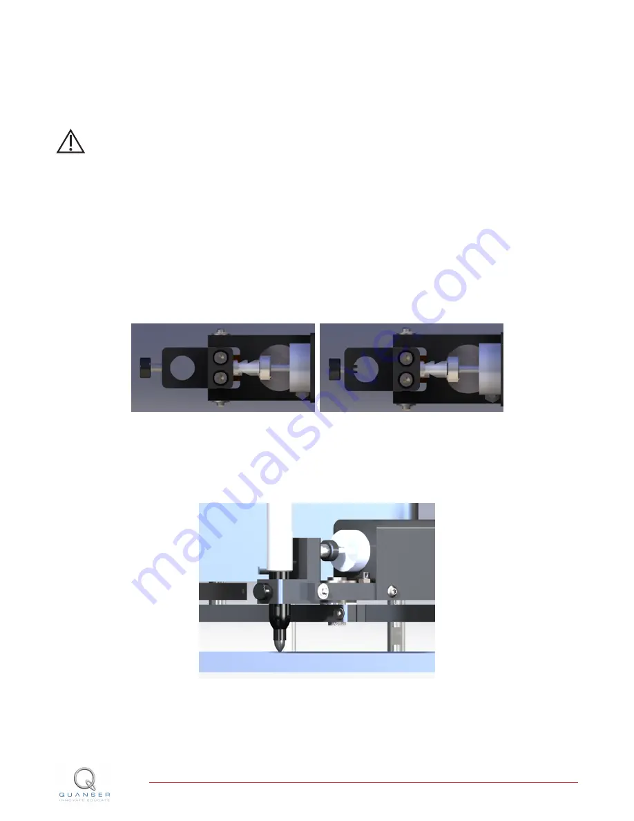
1. Place the robot in a configuration such that the end effector is somewhere in the workspace.

2. Make sure the thumb screw in the end effector is not protruding into the hole (picture on left in Figure 3.1)

where the pen goes. Place the pen in the hole and leave the screw disengaged.

(a) Screw Disengaged

(b) Tightened Screw

Figure 3.1: Thumb screw setup

3. Manually extend the solenoid until it reaches the end of its stroke. Tighten the pen in place at this point with

the thumb screw. This is not the final resting place of the pen so don’t tighten too much.

Figure 3.2: Pen in downward position

4. Allow the solenoid to retract now and loosen the thumbscrew while holding the pen in place. Move the pen

down towards the paper by about 1-2mm and tighten the thumbscrew firmly.

2 DOF PLANAR ROBOT User Manual

DRAFT - September 6, 2013

Summary of Contents for 2 DOF Planar Robot

Page 1: ...2 DOF Planar Robot User Manual 2 DOF Planar Robot Quanser Inc 2013...

Page 2: ...m This document and the software described in it are provided subject to a license agreement Neither the software nor this document may be used or copied except as specified under the terms of that li...

Page 3: ...Component Descriptions 7 3 2 DOF Planar Robot Setup and Configuration 9 3 1 Pen Setup 9 3 2 Calibration Procedure 10 4 Wiring Procedure 11 4 1 Cable Nomenclature 11 4 2 Connection using a Two Channel...

Page 4: ...t robot motions are traced on paper below Figure 1 1 Quanser 2 DOF Planar Robot system Caution This equipment is designed to be used for educational and research purposes and is not intended for use b...

Page 5: ...t PD joint controllers have been implemented The controller gains can be tuned using the slider gains to improve the performance 1 2 5 Closed Loop Cartesian Controller with Forward and In verse Kinema...

Page 6: ...nar Robot components listed in Table 2 1 below are labeled in Figure 2 1 and Figure 2 2 ID Component ID Component 1 Link 1 7 Calibration Posts 2 Link 2 8 Motors w Harmonic Drives 3 Link 3 9 Encoders 4...

Page 7: ...ushes The most likely source for high frequency noise is derivative feedback If the derivative gain is set too high a noisy voltage will be fed into the motor To protect your motor you should always b...

Page 8: ...ontinuous duty actuator This means that the solenoid can be left actuated indefinitely without overheating The solenoid has a stroke with an output force measuring 20 oz at 1 8 stroke and draws 5 5W o...

Page 9: ...tor is not protruding into the hole picture on left in Figure 3 1 where the pen goes Place the pen in the hole and leave the screw disengaged a Screw Disengaged b Tightened Screw Figure 3 1 Thumb scre...

Page 10: ...count to the appropriate value for that location To calibrate the robot follow these instructions 1 Install the stainless steel calibration posts into the set of calibration holes as shown in Figure 2...

Page 11: ...olenoid See the corresponding documentation for more information on these components The cables supplied with the 2 DOF Planar Robot are described in Section Section 4 1 and the procedure to connect t...

Page 12: ...ion to the desired DC motor on the servo e Motor Cable AMPAQ 2x4 pin DIN to 2 pin lock ing This cable connects the output of the AMPAQ L2 power module after amplification to the desired DC motor on th...

Page 13: ...ight Motor connector Power leads to the 2 DOF Planar Robot right DC motor 5 Terminal Board Encoder Input 0 2 DOF Planar Robot Left En coder connector Left motor encoder load shaft angle measurement 6...

Page 14: ...4 shown in Figure 4 1 7 Connect the 5 pin stereo DIN to 5 pin stereo DIN cable from the Left Encoder connector on the 2 DOF Planar Robot panel to Encoder Input 0 on the terminal board as depicted by c...

Page 15: ...Figure 4 2 Connecting the 2 DOF Planar Robot to a Two Channel Voltage Amplifier and DAQ 2 DOF PLANAR ROBOT User Manual DRAFT September 6 2013...

Page 16: ...port link Fill in the form with all the requested software and hardware information as well as a description of the problem encountered Also make sure your e mail address and telephone number are incl...

Page 17: ...REFERENCES 1 Quanser Inc Q2 USB Data Acquisition System User s Guide 2010 2 DOF PLANAR ROBOT User Manual DRAFT September 6 2013...

Reviews: