background image

3

Setup

3.1 Setting up the QBot 2

Follow these steps to setting up the QBot 2:

1. Connect the battery inside the Kobuki robot.

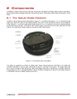
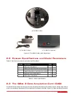
2. Press the power button shown in Figure 2.2c. This should turn on both vehicle and QBot 2 DAQ and Gumstix

computer. After you make sure that this works, turn off the robot and follow the steps below to establish network
connection.

3.2 Establishing Network Connection

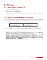
The QBot 2 package comes with a pre-configured wireless router and automatically connects to the WiFi network
Quanser_UVS. It uses TCP/IP connection for communicating with the host computer and/or other

Quanser

r

unmanned vehicles. The Host PC and each of the vehicles must have unique IP addresses and the range of
these addresses are defined below (suggested):

Host PC(s)

192

.

168

.

2

.

10

to

192

.

168

.

2

.

19

Quanser vehicles (Gumstix)

192

.

168

.

2

.

20

to

192

.

168

.

2

.

254

These Steps outlined below for setting up the host computer wireless connection only need to be performed once.

1. Power up and turn on the wireless router.

2. After turning on the router that is provided, wait for about 60 seconds for the wireless network to establish and

then turn on the QBot 2 power and wait for it to boot up (approximately 60 seconds).

3. Connect your PC network card to any of the ports of the router (e.g. port number 1 to 4) using the network

cable provided (you can also connect to the Quanser_UVS or Quanser_UVS-5G wireless network if your
computer has wireless adapters, however, wired connection between your PC and the router is preferred for
better performance). If you choose wireless connectivity between your PC and the router, you should use the
password UVS_wifi to connect to the wifi network.

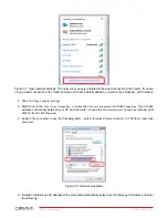
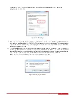
4. Using the

Windows Network Connection

utility in the

Windows Task Bar

, open the

Network and Sharing Center

.

QBOT 2 - User Manual

18

Summary of Contents for QBot 2

Page 1: ...CAPTIVATE MOTIVATE GRADUATE USER MANUAL QBot 2 for QUARC Set Up and Configuration...

Page 2: ...ollections b to create and reproduce adaptations provided reasonable steps are taken to clearly identify the changes that were made to the original work c to distribute and publically perform the work...

Page 3: ...ble through three different block sets the Quanserr Hardware In the Loop HIL block set to read from sensors and or write to outputs the Quanserr Stream API blockset to perform communications over wire...

Page 4: ...crosoft Kinect SDK v1 8 installed http www microsoft com en ca download details aspx id 40278 5 Microsoft Kinect for Windows Developer Toolkit v1 8 installed http www microsoft com en ca download deta...

Page 5: ...by two differential drive wheels with built in encoders The Kobuki comes with a bumper sensor as well as a built in gyroscope and cliff sensors The embedded computer target can access data from these...

Page 6: ...Distance between the left and right wheels 0 235 m h Height of the QBot 2 with Kinect mounted 0 27 m max Maximum speed of the QBot 2 0 7 m s m Total mass of the QBot 2 3 79 kg Table 2 1 QBot 2 specif...

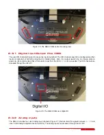
Page 7: ...e Kobuki 12 V 5 A power source see Figure 2 4 Figure 2 3 The QBot 2 DAQ Figure 2 4 The QBot 2 DAQ connectors The QBot 2 DAQ also provides five headers for users to use when integrating additional I O...

Page 8: ...utput needs to be in a known state on power up it is recommended that a 10k resistor is put from the I O to 5 V or GND as needed The DIO channels are accessed through the HIL API Figure 2 6 The QBot 2...

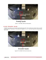
Page 9: ...user encoder input channels Figure 2 8 Each encoder input channel has an A and B pulse as well as a Z index signal The encoders are sampled at 100 kHz The encoder inputs are accessed through the HIL...

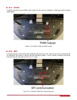
Page 10: ...r PWM outputs 2 3 5 SPI The QBot 2 provides one Serial Peripheral Interface SPI bus Figure 2 10 which is a synchronous serial data bus for interfacing other sensors or devices with the embedded comput...

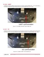
Page 11: ...in the QUARCr help Figure 2 11 The QBot 2 DAQ UART communication port 2 3 7 I2 C The QBot 2 provides one inter integrated circuit I2 C serial bus Figure 2 12 for interfacing with external sensors and...

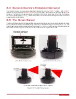
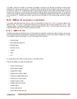
Page 12: ...ter and or other vehicles 2 5 The Kinect Sensor The Microsoft Kinect sensor is an integrated RGB camera and depth sensor used in a variety of experiments Figure 2 13a The Kinect camera provides RGB im...

Page 13: ...HIL blockset it used to communicate with Quanserr data acquisition cards For detailed information on the HIL blockset see the QUARCr HIL user guide in the Matlabr help under QUARC Targets User s Guid...

Page 14: ...the corresponding HIL Initialize through its name The HIL blocks will interface to the DAQ specified in the HIL Initialize Board type parameter qbot2 The HIL Read Write block is used to read sensor m...

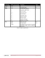
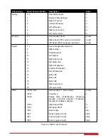
Page 15: ...LED1 green colour 11 LED2 red colour 12 LED2 green colour 13 Enable 3 3V power 14 Enable 5V power 15 Enable 12V 5A power 16 Enable 12V 1 5A power Other 2000 Right wheel speed m s 2001 Left wheel speed...

Page 16: ...tral bumper 10 Left bumper 11 Right wheel drop 12 Left wheel drop 13 Right cliff detected 14 Central cliff detected 15 Left cliff detected 16 Button B0 17 Button B1 18 Button B2 19 Right overcurrent 2...

Page 17: ...when a new frame is available so that it can be used to trigger image processing only once per frame The Kinect Get Depth block is used to output a depth mapped image at the specified resolution The...

Page 18: ...r vehicles Gumstix 192 168 2 20 to 192 168 2 254 These Steps outlined below for setting up the host computer wireless connection only need to be performed once 1 Power up and turn on the wireless rout...

Page 19: ...identi ed network connection and click Properties If you chose wireless connectivity between your PC and the router choose the Wireless Network Connection instead right click on it and click Propertie...

Page 20: ...e router check network connectivity and your IP address before going to the next steps 10 If the QBot 2 is powered on the QBot 2 can be pinged by typing ping IP of the QBot 2 in the Run box in Windows...

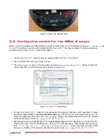
Page 21: ...ssary Figure 3 6 Figure 3 6 QUARCr Option Menu 4 In order to run the QUARCr model on the target vehicle the target s IP address must be specified To setup the default target address for all linux duov...

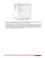
Page 22: ...mpiled and downloaded to the target If the wireless connection to the vehicle has been established a QUARCr console can be opened to show additional messages and progress during model compilation by g...

Page 23: ...umstix and antenna are properly connected Make sure the Gumstix and antenna are securely connected and retry the above steps to establish a wireless connection Recycle the power or turn on the robot a...

Page 24: ...on Time block to determine their execution time during each sample instant This helps identify the bottlenecks in the model blocks subsystems with the highest execution time and can identify blocks su...

Page 25: ...the QUARCr menu under QUARC Clean all will remove all generated code and compiled code for the current model but this will only free up the space used by the current model To view all models currently...

Page 26: ...ch Support link Fill in the form with all the requested software and hardware information as well as a description of the problem encountered Also make sure your e mail address and telephone number ar...

Page 27: ...mobile robotics from vibration analysis resonance and planar position control to sensors computer vision guided control to unmanned systems control All of the experiments platforms are compatible with...

Reviews: