• SCREEN NO.4
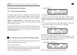
Minimum recorded input voltage from the last switching on of
the device. It is reset when the regulator is switched off. It can
also be reset by pressing the middle button.
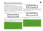
• SCREEN NO.5
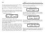
The maximum recorded input voltage from the last switching on
of the device. It is reset when the regulator is switched off. It can
also be reset by pressing the middle button.
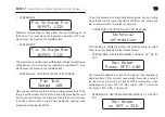
• SCREEN NO.6. COOLING SYSTEM TEST SCREEN
Here you can test the operation of the cooling system fans. To do
this, press the middle button of the device. By pressing the right
button, you will increase the number of fan rotations per minute.
It will be possible hear a slight noise inside the housing while
gradually increasing the RPMs.
To exit the menu, press the middle button again. You can safely
move further on the menu - the device will return the cooling sys-
tem to normal mode. The value is not saved.
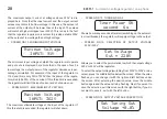
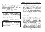
• SCREEN NO.7. TECHNICAL SECTION HEADING
This heading is displayed before the technical data is listed.
There is no functionality for the middle button.
• SCREEN NO.8. DEVICE MAXIMUM CURRENT AT THE IN-
PUT
The maximum allowable current at the input of the regulator is
displayed here. If this current consumption threshold is exceed-
ed, the device will switch off, but at different intervalsL when
overloaded more than 125% of this current - after 12 seconds,
more than 150% - after 1.5 seconds.
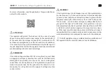
• SCREEN NO.9. DEVICE MAXIMUM CURRENT AT THE OUT-
PUT
Max Amper
on OUT = 32A
19
19
Fix Voltage Min
INPUT: 123V
Fix Voltage Max
INPUT: 321V
Fan Test
Speed 180
Technical
information
QUANT-7
Automatic voltage regulator, one-phase
Max Amper
Power OFF: 60A


