background image

UANTA COMPUTER INC.                      


L5TD Monitor


_____________________________________________________________________________________________________________________  

__________________________                     _______ ___________________________________                     _______ _________________________ 

L5TD 

Service Menu Rev 1B               

                                                                                                               Page: 29  

- Quanta Confidential - 


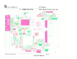
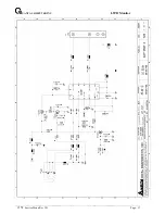
Button Board Silkscreen 


Button Board Layer Bottom 


Summary of Contents for L5TD Serial

Page 1: ...101551 111505 July 25 2003 Revision 1B Issued By T H Chu Checked By Benjie Tsao _________________________________________________________________________________ The release of this document is under...

Page 2: ...___________________________ _____________________________________________________________________________________________________________________________ L5TD Service Menu Rev 1B Page 2 Quanta Confide...

Page 3: ..._________ L5TD Service Menu Rev 1B Page 3 Quanta Confidential Content Chapter Page A WARNING 4 B SAFETY PRECAUTIONS 5 1 DIMENSIONS 6 2 GENERAL INFORMATION 8 3 SPECIFICATIONS 9 4 THEORY OF OPERATION 14...

Page 4: ...WARNING This service information is designed for experienced repair technicians only and is not designed for use by the general public It does not contain warnings or cautions to advise non technical...

Page 5: ...ermanently attached Any attempt to replace another adapter could result in serious problem on the display 4 LEAKAGE CURRENT HOT CHECK 4 1 Plug the AC cord directly into the AC outlet Do not use an iso...

Page 6: ...___________________________________________________________ _____________________________________________________________________________________________________________________________ L5TD Service M...

Page 7: ..._______________________________________________________________________ _____________________________________________________________________________________________________________________________ L5...

Page 8: ...Languages function is excellent and new man machine interface Anyone is able to set up the picture as he like through OSD menu 2 2 3 Self Test function Self Testing picture comes out by pushing any ke...

Page 9: ...menu includes the following function CONTRAST BRIGHTNESS H POSITION V POSITION COLOR TEMPERATURE CLOCK PHASE LANGUAGE VOLUME POWER ON RECALL 3 1 4 CONTRAST and BRIGHTNESS can be directly controlled w...

Page 10: ...for all conditions of line in voltage Maximum power consumption 35 Watts 3 5 2 2 Power Management The Power Management System complies to TCO 03 standards MODE H SYNC V SYNC COLOR OF POWER LED POWER...

Page 11: ...37 879 48 077 46 875 48 363 56 180 60 023 V Freq Hz 70 087 59 942 72 809 75 000 70 082 56 250 60 317 72 188 75 000 60 004 69 960 75 029 Pix Rate MHZ 25 175 25 175 31 500 31 500 28 320 36 000 40 000 50...

Page 12: ...ypical 250 cd m2 min 200cd m2 3 5 6 3 Brightness variation 3 5 6 4 Contrast ratio CR 3 6 ENVIRONMENTS The environmental conditions are in accordance to IEC 721 Operating Temperature 5 C 40 C Humidity...

Page 13: ...rvice Menu Rev 1B Page 13 Quanta Confidential 3 7 REGULATORY STANDARDS 3 7 1 Safety standards This monitor applies to various safety EMI standards May refer to the logo label 3 7 2 EMC standards FCC p...

Page 14: ...4 1 1 Flat panel controller MST8016 U2 The heart of the system board is MST8016 The MST8016 is a graphics processing IC for LCD monitor It provides all key IC functions required for LCD panel On chip...

Page 15: ...he keypad the backlight LED audio and non volatile RAM using general purpose input output I O pins Pin No Pin Name Pin Usage 20 P1 2 SDA Data signal for serial communication 21 P1 3 SCL Clock signal f...

Page 16: ...3A Electrical specification described as below 4 2 3 Audio amplifier TDA7496 The TDA7496 on the power board is a 2 channel audio power amplifier capable of delivering 1W of continuous average power t...

Page 17: ..._______________________________________________________________________________________________________________ L5TD Service Menu Rev 1B Page 17 Quanta Confidential 5 DISASSEMBLY INSTRUCTIONS 1 Stand...

Page 18: ...__________________________________________________________________________________________ L5TD Service Menu Rev 1B Page 18 Quanta Confidential 3 Inverter cover Inverter board removal 1 remove two scr...

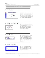
Page 19: ...ON 1 OSD Menu Trigger OSD Main Menu Clear OSD 2 UP 1 Select OSD Main Menu Item 2 Trigger Brightness Contrast Menu 3 DOWN 1 Select OSD Main Menu Item 2 Trigger Brightness Contrast Menu 4 POWER Switch P...

Page 20: ...ger this menu appear for Brightness and Contrast adjust This menu will display about 45 seconds When user press the Menu key under none OSD status will trigger this menu appear for detail parameters a...

Page 21: ...the brightness of the display Contrast Left Right Adjust the difference between the light and dark areas When Display timing changed this dialog will appear about 5 seconds And this feature only enab...

Page 22: ...ars or stripes visible on the screen background The horizontal screen size will also change PHASE Adjust to remove any horizontal distortion and clear or sharpen the image of characters V Position Adj...

Page 23: ...alue SPREAD Adjust chip set internal frequency spread effect for EMI testing This page only visible in factory mode AUTO BURN Use the chip set internal pattern for hot running monitor panel and invert...

Page 24: ..._______________________________________________________ L5TD Service Menu Rev 1B Page 24 Quanta Confidential 7 NECESSARY EQUIPMENT LIST Item 1 Personal Computer with Windows 98 Me XP 2 Luminance Meter...

Page 25: ...its x dual pixel 36bits Panel power clock Hs Vs DEN Control signal ADC VGA cable R G B Hs Vs PC VGA port DDC signal 12V 3 3V Output to AD board AC DC power Inverter Audio Amplifier L5TD Block Diagram...

Page 26: ...__________________________________________________________________________ __________________________ _______ ___________________________________ _______ _________________________ L5TD Service Menu Re...

Page 27: ..._____________________________________________________________________________________ __________________________ _______ ___________________________________ _______ _________________________ L5TD Serv...

Page 28: ...___________________________________________________________________________________ __________________________ _______ ___________________________________ _______ _________________________ L5TD Servic...

Page 29: ...______________________________________________________________________ __________________________ _______ ___________________________________ _______ _________________________ L5TD Service Menu Rev 1B...

Page 30: ...VGA_SDA_O VGA_SCL_O R14 1K 6 Title Size Document Number Rev Date Sheet of VGA AND TMDS INPUT CONTENT 1 6 Wednesday July 16 2003 D SCHEMATIC1 R17 1K 6 VSYNC C12 22P 6 NC IN V Quanta Computer Inc PROJE...

Page 31: ...4 AVSS_DVI 42 GNDP 10 GNDP 20 GNDP 85 GNDP 95 GNDP 115 GNDP 127 GNDC 19 GNDC 86 GNDC 96 GNDP 105 GNDC 116 XIN 33 XOUT 34 RA1P 108 RA1N 109 RA2P 110 RA2N 111 RA3P 112 RA3N 113 GA1P 98 GA1N 99 GA2P 100...

Page 32: ...EY_IN LED_G 2 0mm pitch 90 E T 4607 5Pin IN_O KEY_O TO BUTTON BOARD LED_R KEY_IN SS0003 LED_R SDA_O SCL VGA SDA VGA HP MCU 3 12V 3 3V 2 5V VDD3V3 VCC12 C53 0 1U 6 C54 0 01U 6 NC Q3 AIC1739 VIN 3 VOUT...

Page 33: ...C C E VDDCTRL_2 4 B 2 C73 2200P 6 1 2 2 Q9 SI2301DS 3 2 1 G R70 100K 6 Q10 DTC144EUA 2 3 1 R68 82K 6 3 3 C74 2200P 6 1 2 D C76 330U 16V S LCDVCC C75 0 1U 6 1 2 R69 47K 6 1 2 VCC12 LCDVCC 1 C69 2200P 6...

Page 34: ...3 2 4 LEDG LEDR SW3 HDK632R ST 1 3 2 4 SW4 HDK632R ST 1 3 2 4 POWER ON OFF SW5 HDK632R ST 1 3 2 4 SW6 HDK632R ST 1 3 2 4 G O LED1 L 3WYGW YELLOW GREEN A2 C A1 SW7 HDK632R ST 1 3 2 4 LEDR GND GND GND...

Page 35: ...Power Inverter Board Schematic...

Page 36: ..._________________________________________________________________________________________________________ __________________________ _______ ___________________________________ _______ _______________...

Page 37: ..._________________________________________________________________________________________________________ __________________________ _______ ___________________________________ _______ _______________...

Page 38: ..._________________________________________________________________________________________________________ __________________________ _______ ___________________________________ _______ _______________...

Page 39: ...__________________________________________________________________________________________ __________________________ _______ ___________________________________ _______ _________________________ L5TD...

Page 40: ..._________________________________________________________________________________________________________ __________________________ _______ ___________________________________ _______ _______________...

Page 41: ..._____________________________________________________________________________ __________________________ _______ ___________________________________ _______ _________________________ L5TD Service Menu...

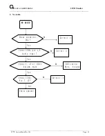
Page 42: ...________________________ L5TD Service Menu Rev 1B Page 42 12 TROUBLE SHOOTING HINTS 1 No Power NO POWER Check CN6 in AD board Check CN6 pin1 4 3 3V correct Change 14pins cable No Change Power board No...

Page 43: ...____________________ _______ ___________________________________ _______ _________________________ L5TD Service Menu Rev 1B Page 43 2 No Audio NO AUDIO Check connector CN2 Check IC301 pin 1 5 Audio in...

Page 44: ...__________________________ _______ ___________________________________ _______ _________________________ L5TD Service Menu Rev 1B Page 44 3 3 No Characters Missing one Color No Characters Missing Col...

Page 45: ...Q10 3 BAM23010Z05 TRANSISTOR MOSFET SI2301DS 12V 2 3A 2 Q7 Q9 3 BAN70020Z13 TRANSISTOR MOSFET 2N7002E 60V 250MA 2 Q4 Q5 3 CH02206J909 CAPACITOR CHIP 22P 50V 5 NPO 0603 6 C40 C41 C49 C50 C51 C52 3 CH2...

Page 46: ...M B L5TD MST MB 2L 98 125 REVD 1 3 CH21006K917 CAP CHIP 1000P 50V 10 X7R 0603 1 C44 2 DFHD05MR633 CONN DIP HEADER 5P 1R MR P2 0 H5 1 1 CN4 2 DFHD12MR251 CONN DIP HEADER 12P 2R MR P2 54 H5 1 1 CN6 2 DF...

Page 47: ...247 1000MM T0 6 230 4 MBL70002016 NUT M4 0 7 5 T0 3 MBL70002 REV3A 2 3 FCL5T001018 POWER SHIELD MYLAR L5TL FCL5T001 REV3A 1 2 AA0150XG208 LCD TFT CLAA150XG08 15 1024 768 XGA 0 2 AA0150XG216 LCD TFT C...

Page 48: ...5 5 2 MF40080IBJ1 SCREW F4 0 8 I NI 2 2 MS40100T138 SCREW M4 0 10 T MC 3 1 27L5TCSMA27 L5TD CHASSIS ASSY BLACK 1 2 DDL5RLPB006 CABLE ASSY L5RL MB POWER 12P REV1A 1 2 MF30080BBJ5 SCREW F3 0 8L B NI 2...

Page 49: ...6018 LCD BKT R L5TD FAL5T006 REV3A 1 2 FBL5T001017 AL FOIL BKT L5TL FBL5T001 REV3A 2 2 FBL5T006019 GND PLATE S L5TD FBL5T006 REV3B 1 2 GBL5T003010 SPEAK SPONGE L5TL E GBL5T003 REV3A 2 2 33L5TLSMA11 L5...

Page 50: ...1B Page 50 2 DM333181801 POWER CORD SP 023 IS 14H05VV F3P 1 8M EU 1 Screw spare parts PART NO DESCRIPTION MF40080IBJ1 SCREW F4 0 8 I NI MF30080BBJ5 SCREW F3 0 8L B NI MM40080BCI5 SCREW M4 0 8 B NI NYL...

Page 51: ...TORY 2 Auto Color RUN For AD converter calibration on R G and B gain offset 4 Select Color Update RUN 5 Press OSD select COLOR into 6500 and check by color analysis If adjustment Press OSD select FACT...

Reviews: