J
UMPERS
AND
C
ONNECTORS
M
AINBOARD
C
ONNECTORS
AND
J
UMPERS
5-1
5.1. Mainboard Connectors and Jumpers
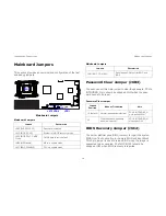
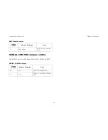
Mainboard Connectors and LEDs
This section provides information on basic connectors and
LEDs on system mainboard.
Mainboard Connectors and LEDs
Mainboard Connectors and LEDs
L
OCATION
C
ONNECTOR
1
PCIe x16 riser slot 4 (J1H1)
2
PCIe x16 riser slot 3 (J1G1)
3
SATA1_4 port (J1C2)
1
2
3
4
5
6
7
8
9
10
11
14
12
13
15
16
17
4
PCIe x16 riser slot 2 (J1C1)
5
IB act/link LED (x2) (DS1A9, DS1A10)
6
IB port (J2A1)
7
USB 2.0 port (x2) (J3A1)
8
VGA port (J4A1)
9
NIC2 RJ45 LAN port (JA5A1)
10
NIC1 RJ45 LAN port (JA5A2)
11
PCIe x16 riser slot 1 (J6A1)
12
CPU1 DIMM sockets (2x4) (from CPU: J5K2, J6K1,
J6K2, J6K3, J1G2, J1G3, J2G2, J2G3)
13
CPU1 (U3J1)
14
CPU0 DIMM sockets (2x4) (from CPU: J5G1, J6G1,
J6G2, J6G3, J1D2, J1D3, J2D3, J2D4)
15
CPU0 (U3F1)
16
ID LED/ status LED (DS3A1/ DS3A2)
17
SATADOM Connector
Mainboard Connectors and LEDs (Continued)
L
OCATION
C
ONNECTOR
Summary of Contents for STRATOS S210 Series S210-X2A2J
Page 21: ...SAFETY INFORMATION XXI ...
Page 23: ...About the Server Chapter 1 ...
Page 33: ...Installing Hardware Chapter 2 ...
Page 106: ...BIOS Chapter 3 ...
Page 166: ...BMC Chapter 4 ...
Page 229: ...Jumpers and Connectors Chapter 5 ...
Page 236: ...Rail Kit Assembly Chapter 6 ...
Page 240: ...Troubleshooting Chapter 7 ...
Page 245: ...Installation and Assembly Safety Instructions Chapter 8 ...
Page 249: ...Safety Information Chapter 9 ...
Page 258: ...Regulatory and Compliance Infor mation Chapter 10 ...


