J
UMPERS
AND
C
ONNECTORS
M
AINBOARD
J
UMPERS
5-5
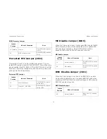
Protected RTC Jumper (J6C3)
This jumper is used to be the CMOS clear jumper. The pro-
tected RTC jumper is tied to PCH's RTCRST_N pin. When this
pin is asserted, the RTC_PWR_STS bit (D31:F0:A4h.2) in PCH
will be set, and those configuration bits in the RTC power well
will be set to their default state.
ME Disable Jumper (J6B6)
When this 3-pin jumper is set, it will bypass ME and sets the ME
FW in recovery mode, which enables the user to update ME
FW code when necessary. PCH's GPIO [57] should be
strapped LOW when an ME FW update is required.
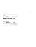
BMC Disable Jumper (J6C1)
When this 2-pin jumper is set, it sets the BMC FW in update
mode, which enables the user to update BMC FW code when
necessary. BMC's GPIO [1] should be strapped LOW when an
BMC FW update is required.
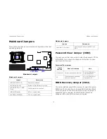
BIOS Recovery Jumper
J
UMPER
P
OSITION
M
ODE
OF
O
PERATION
N
OTE
1-2 (default)
Normal
PCH GPIO [55] is pulled
HIGH
2-3
BIOS recovery mode
PCH GPIO [55] is pulled
LOW
Protected RTC Jumper
J
UMPER
P
OSITION
M
ODE
OF
O
PERATION
N
OTE
1-2
Normal (default)
PCH RTCRST_N pin is
pulled HIGH
2-3
Clear RTC_RST REG
PCH RTCRST_N pin is
pulled LOW
ME Disable Jumper
J
UMPER
P
OSITION
M
ODE
OF
O
PERATION
N
OTE
1-2
Normal (default)
PCH GPIO [57] is pulled
HIGH
2-3
ME disable
PCH GPIO [57] is pulled
LOW
BMC Disable Jumper
J
UMPER
P
OSITION
M
ODE
OF
O
PERATION
N
OTE
NC
Normal (default)
BMC GPIO [1] is pulled
HIGH
Summary of Contents for STRATOS S210 Series S210-X2A2J
Page 21: ...SAFETY INFORMATION XXI ...
Page 23: ...About the Server Chapter 1 ...
Page 33: ...Installing Hardware Chapter 2 ...
Page 106: ...BIOS Chapter 3 ...
Page 166: ...BMC Chapter 4 ...
Page 229: ...Jumpers and Connectors Chapter 5 ...
Page 236: ...Rail Kit Assembly Chapter 6 ...
Page 240: ...Troubleshooting Chapter 7 ...
Page 245: ...Installation and Assembly Safety Instructions Chapter 8 ...
Page 249: ...Safety Information Chapter 9 ...
Page 258: ...Regulatory and Compliance Infor mation Chapter 10 ...


