QA402 User Manual
15
ADC Overflow:
Indicates the ADC had packets, but the USB didn’t take them in time and so may have been
lost. Sometimes, this message can be a bit pessimistic and what was flagged as an error might not have been
an error. When this message appears, either re-acquire the signal or carefully inspect the time-domain signal
for a dropout.
Atten
: Indicates the front-end attenuator is active.
DAC Underflow
: Indicates the DAC needed packets, but the USB hadn’t delivered them yet. Sometimes, this
message can be a bit pessimistic and what was flagged as an error might not have been an error. When this
message appears, either re-acquire the signal or carefully inspect the time-domain signal for a dropout.
FFT Too Small
: Indicates the FFT might be too small for the displayed activity (usually this will be shown in
Frequency Response (FR) mode).
FP I2S Clip
: Indicates the signal being sent to the front panel is clipping.
FR Gain
: Indicates the FR mode graph is showing gain instead of absolute level.
FR Ref R
: Indicates the FR mode graph is using the right channel for the reference.
Input Gain
: Indicates the user-specified input gain.
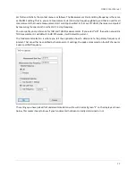
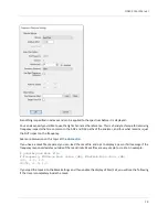
Latency Compensation
: Indicates the user-specified latency compensation. Often, when working with
Bluetooth or other DSP-based equipment the latency compensation will need to be increased to ensure the
signal is properly captured (see Edit->Settings).
Mirror
: Indicates Generator 1
settings are being mirrored to the PC’s primary audio
device.
Mute L
: Indicates the left channel is muted.
Mute R
: Indicates the right channel is muted.
No Channels Selected
: Indicates no data has been selected for display. Select L, R or both.
Caution! Input Range Test Mode
: Indicates the input level is unclipped and can display levels in excess of safe
operation. This also indicates the front-end attenuator is always active. This mode is used for testing by
authorized personnel that need to verify measurement accuracy at higher voltages.
Output Gain
: Indicates the user-specified output gain.
Output Displayed
: Indicates the output traces are being displayed, rather than the input traces.
Range
: Indicates that during the last acquisition and overload was encountered and the attenuator was
engaged.
Pause
: Indicates a non-zero user-specified pause time has been entered (see Edit->Settings). This pause will
occur between acquisitions and can be helpful in dealing with higher latency systems OR in systems where you
want to careful limit the average power delivered to a load (by making measurements less frequently).
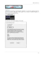
A Weighting
: Indicates A-weighting has been applied to the displayed trace.
User Weighting
: Indicates the user-specified weighting has been applied to the trace. This will also include the
file name of the weighting file.


