background image

QA402 User Manual 


Online Documentation 

This  manual  focuses  primarily  on  the  functionality  of  the  hardware  and  the  software.  The  application, 
measurement techniques and tradeoffs are a substantial topic especially when the experience level of users is 
considered.  Additional  sources  of  information  can  be  found  at  th

Github  Wiki

  for  the  QA40x,  and  the 

QuantAsylum Forum


In the Box  

The  box  contains  a  QA402 Audio  Analyzer.  We  do  not ship cables  with our  products.  The  software  for  the 
products may be downloaded from GitHub. The link for QA40x downloads is located 

here


See the 

Github QA40x Getting Started Wiki

 for ideas on accessories.  

Important Things to Know 

This section covers some important details about the analyzer.  

Model Number 

In this document, the phrase 

QA40x hardware

 refers to the QA403 and QA402 hardware. The phrase 

QA40x 

software

  refers  to  the  application  used  to  interface  with  the  QA40x  hardware.  The  family  of  hardware 

products (QA402 and QA403 hardware) use the same QA40x software. 

Ground Reference 

There are two grounds to consider on the QA40x. The USB connection shares a ground with the PC, which in 
turn shares a ground with the power distribution in your office. The audio side of the QA40x analyzer is isolated 
from the USB ground: it is 

floating. 

When you connect the QA40x hardware to a device-under-test (DUT) to 

make a measurement, you will need to establish a common reference point for the measurements. The DUT 
will have its own ground (which may be similar to the PC ground). The isolation provided by the QA402 ensures 
noise related to ground currents is eliminated.  

If your D

UT is also floating (which is common if the DUT is powered from a “brick”

-style wall adaptor, then you 

can reduce powerline hum in your measurements by connecting the floating ground to an earth ground. 

BNC Input Voltages 

The inputs on the QA40x hardware are designed for AC inputs, with some DC present. The DC will be blocked 
by the input capacitor and cannot be measured. DO NOT EXCEED THE SPECIFIED LIMITS, OR YOU WILL DAMAGE 
THE QA40x AND/OR MIGHT INJURE YOURSELF. 

BNC Output Voltages 

The BNC outputs are DC coupled. They cannot withstand inadvertent connections to DC voltages where more 
than 10 mA of current might flow. Extended shorting of the outputs will result in an increase in temperature 
of the output stage, which can cause a permanent shift in performance. 

Summary of Contents for QA40 Series

Page 1: ...QA40x User Manual Revision 1 20 February 2022...

Page 2: ...esponsible for shipping to us and we will be responsible for shipping it back to you Devices that have suffered a failure due to operation in excess of specified parameters can usually be repaired for...

Page 3: ...A40x Analyzer Features 6 Analyzer Front Panel 6 LEDs 6 Expansion Connector 7 BNC Inputs and Outputs 7 Understanding Differential Measurements 8 Rear Panel Summary 8 Electrical Characteristics of the C...

Page 4: ...n Settings 19 Weighting 20 Windowing 21 Measurements 21 Generators 23 Sine Generation 24 Multitone 25 White Noise 27 Expo Chirp 27 Full Scale Input 29 Run Stop 30 Run Stop Context Menu 31 Cursors 32 O...

Page 5: ...shares a ground with the PC which in turn shares a ground with the power distribution in your office The audio side of the QA40x analyzer is isolated from the USB ground it is floating When you conne...

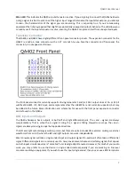
Page 6: ...ht Outputs 24 bit ADC and DAC for QA402 and 32 bit ADC and DAC for QA403 Fully Isolated from the PC 8 Input Gain Stages from 0 dBV to 42 dBV full scale the maximum input is 32 dBV 4 Output Gain Stages...

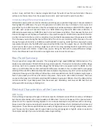
Page 7: ...ther than 48 kSPS are not currently supported but may be added in the future More information and schematics for use with the front panel expansion connector can be found on the QA40x BNC Inputs and O...

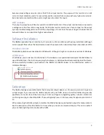
Page 8: ...ases Rear Panel Summary The rear panel has a single USB connector This is designed for high speed 480Mbps USB connections The device consumes between 700 and 900 mA during normal operation The device...

Page 9: ...Windows Version The QA40x application was developed on Windows 10 although it might run on previous versions of Windows USB Drivers On Windows you do not need to install drivers The hardware uses spe...

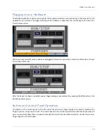
Page 10: ...onfirmation as shown in the lower left corner After the device has been connected you can begin making a measurement by pressing the RUN button in the Run Stop control group Button and Control Panel O...

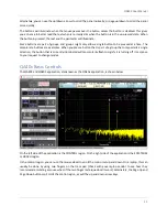
Page 11: ...p that only permits a single selection the button that is currently illuminated will momentarily flash to signify it is turning off in response to your request to change modes QA40x Basic Controls The...

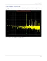
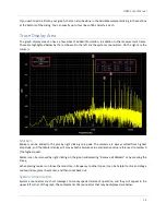
Page 12: ...er Manual 12 Measurement Display Area At the top of the trace display is the measurement display area Measurements can be added by clicking in this region Clicking will bring up the Add Measurement di...

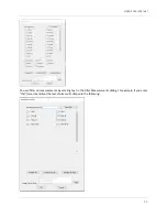
Page 13: ...QA402 User Manual 13 You can filter on measurements by entering text in the Filter Measurements dialog For example if you enter thd case insensitive the test choices will collapse to the following...

Page 14: ...y right clicking on a peak The markers are always sorted from highest amplitude and the tabular display will convey both absolute value and relative value referenced to marker 0 the highest peak Marke...

Page 15: ...ent the latency compensation will need to be increased to ensure the signal is properly captured see Edit Settings Mirror Indicates Generator 1 settings are being mirrored to the PC s primary audio de...

Page 16: ...nd hold After 1 second the menu will open This is useful if you are using a finger on a touch screen 2 Mouse right click The menu will immediately open A sample control stack is shown below The heavy...

Page 17: ...specify The context menu for the dBV button is shown below In this dialog you can specify the units for the Y axis Normally dBV is used But you can also specify dBu You can also specify if you have a...

Page 18: ...Or you could specify the level in dBr This is useful if for example you know that a mic should generated a certain output at a given sound pressure level When using the dBr setting you can also overri...

Page 19: ...he averaging button will increase or decrease the average count by one If you click while pressing the CTRL button the count will change by 5 counts When averaging you might wish to re start the avera...

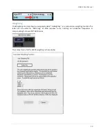
Page 20: ...you apply standard A Weighting or a custom User weighting function The latter can be useful for flattening an RIAA response curve notching out undesired frequencies or compensating for known DUT defic...

Page 21: ...ements You can quickly select the types of measurements you d like to make from this control group The buttons are one shot in that they don t stay lit If you press GAIN and you don t currently have a...

Page 22: ...ecify your preference for THD and THD N measurements If you select dB then when you add a THD measurement it will default to dB Otherwise it will default to percent The fundamental selection is where...

Page 23: ...group we can select one of four modes of operation Sine Gen Multitone White Noise and Expo Chirp Overall the QA40x has 5 modes of operation as shown in the block diagram below The fifth mode of opera...

Page 24: ...exponentially swept in frequency from 20 Hz to Nyquist The exponential nature means you spend more time at lower frequencies and less time at higher frequencies But your energy per Hz is the same Sin...

Page 25: ...sult in changes that step 1 kHz 2 kHz 3 kHz etc Multitone The multitone context menu is shown below Here you can specify the number of tones per octave For example if you specify 1 tone per octave the...

Page 26: ...ines however is around 0 dBV But the real challenge is in the time domain Notice that even though each sine is just 100 mV in amplitude the total output level has exceeded 4V peak in places Be aware o...

Page 27: ...g is done when windowing is non zero 1 A complex division is done between the output waveform over the input waveform This yields the frequency response 2 A reverse FFT is done on the complex division...

Page 28: ...act on the frequency See more discussion on this topic at the QA40x Wiki If you have a mask file prepared you can load the mask file and opt to display a pass or fail message if the frequency response...

Page 29: ...maximum input to the analyzer is 32 dBV with a max DC of 40V and a max ACPEAK DC of 56V Those limits must always be respected even if you are on the 42 dBV input range The concept of full scale input...

Page 30: ...sample rate changes In general the performance of the converters is better at lower sample rates If your measurement task doesn t require frequencies beyond 20 kHz or so stick to the 48K sample rate...

Page 31: ...r Manual 31 Run Stop Context Menu The context menu for the Run Stop button is shown below Triggered Acquisition The Triggered Acquisition is discussed in more detail on the QA40x Wiki article Triggere...

Page 32: ...FS signal will be 18 dBV And if you specify the 8 dBV output range and a 20 dBFS volume then the max output will be 12 dBV Cursors The cursor control block is shown below You can add one or two cursor...

Page 33: ...QA402 User Manual 33 The cursors also work in the time domain and the legend will also show 1 period allowing you to quickly learn the frequency at a given point in time...

Page 34: ...FT you can emit a single short burst of sine For example a 1K FFT at 48Ksps will result in a 20 mS burst of signal Emitting a single one of these bursts can be helpful as you are trying to learn the l...

Page 35: ...een from the webpage linked below while the QA40x application is running When you click on this link the QA40x application will generate a web page of all available tests including descriptions of eac...

Reviews: