QA402 User Manual
8
on the L- input, and treat the L+ input as a single ended input. If you do not use the input terminator, then you
will see some thermal noise from the unused input resistor, which will raise the overall noise floor.
Understanding Differential Measurements
Differential measurements can create confusion even among very experienced engineers. Some examples will
help highlight the differences. If you set the generator to 0 dBV and connect an to an Input+ and
ground the Input- via BNC terminator, then the measured input will be reported as 0 dBV. With the output set
to 0 dBV, each output will measure 1Vrms on a DVM relative to ground (the BNC outer conductor). A
differential measurement on a DVM (from Out+ to Out-) will measure as 2Vrms. This is because the Out+ and
Out- are 180 degrees out of phase with each other. If you set the output to -10 dBV and connect both the Out+
and Out- connectors to the In+ and In- connectors, then the QA402 measurement will show a peak of -4 dBV.
This is because you are driving the inputs differentially. This can be very confusing to first-time users: You are
driving the inputs at 316 mVrms (-10 dBV), and yet the QA402 is reporting -4 dBV. But this is precisely the same
measurement reported by the DVM when you placed the DVM across the outputs. Keep in mind the QA402
inputs have no idea if you are driving a single input with 1Vrms and grounding the other input OR if you are
driving both inputs with 0.5Vrms. In both cases, you are hitting the ADC with the same differential voltage.
That is, the differential input of the ADC is seeing 0.5Vrms on each input in both cases.
Rear Panel Summary
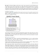
The rear panel has a single USB connector. This is designed for high speed (480Mbps) USB connections. The
device consumes between 700 and 900 mA during normal operation. The device is not sensitive to USB voltage
variations, but it can be sensitive to USB voltages that fall below 4.6V as measured inside the QA402. For this
reason, use USB cables that are short and have 24 AWG power conductors. You can often read the wire gauge
directly off the side of the USB cable. Note that some computers may employ very strict current sensing on the
USB current flowing out of the USB port. When the current exceeds 500 mA, the PC hardware might signal a
fault. If you suspect your PC has strict limits on the power, then you can use a USB Y connector. These are
connectors that plug into 2 USB ports and allow USB hardware to pull up to 1000 mA. One of the USB ports has
no data connection. It just takes power from the second port. Alternately, most low-cost USB hubs that are
self-powered do no sensing or limiting at all.
Electrical Characteristics of the Connectors
BNC Inputs
The 4 audio signal inputs pass through a 4.7uF series capacitor, followed a series 470 ohm resistor, and followed
by a shunt resistor divider with a total impedance of 100K ohms. The corner frequency of this input network is
about 0.4 Hz. The input DC blocking capacitor is an aluminum electrolytic non-polarized, with a 50V rating.
Keep in mind that aluminum electrolytic capacitors have limited lifetimes that is dictated by their stress and
temperature. These lifetime specifications are usually at high ripple currents and high temperatures, which
won’t be seen by the analyzer. But it’s a good idea to not
leave large signals or high DC values connected to
the analyzer overnight if you are not actively measuring something.


