background image

FORM QTC3-EG6 (1118)

QUANTECH

39

ELASTOMERIC ISOLATOR

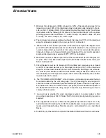
1.  Minimum Circuit Ampacity (MCA) is based on 125% of the rated load amps for the 

largest motor plus 100% of the rated load amps for all other loads included in the cir-

cuit, per N.E.C. Article 430-24. If the optional Factory Mounted Control Transformer 

is provided, add the following MCA values to the electrical tables for the system 

providing power to the transformer: -17, add 2.5 amps; -28, add 2.3 amps; -40, add 

1.5 amps, -46, add 1.3 amps; -58, add 1 amps.

2.  The minimum recommended disconnect switch is based on 115% of the rated load 

amps for all loads included in the circuit, per N.E.C. Article 440.

3.   Minimum fuse size is based upon 150% of the rated load amps for the largest motor 

plus 100% of the rated load amps for all other loads included in the circuit to avoid 

nuisance trips at start-up due to lock rotor amps. It is not recommended in applica-

tions where brown outs, frequent starting and stopping of the unit, and/or operation 

at ambient temperatures in excess of 95ºF (35ºC) is anticipated.

4.  Maximum fuse size is based upon 225% of the rated load amps for the largest mo-

tor plus 100% of the rated load amps for all other loads included in the circuit, per 

N.E.C. Article 440-22.

5. 

Circuit breakers must be UL listed and CSA certified and maximum size is based 

on 225% of the rated load amps for the largest motor plus 100% of the rated load 

amps for all other loads included in the circuit. Otherwise, HACR-type circuit break-

ers must be used. Maximum HACR circuit breaker rating is based on 225% of the 

rated load amps for the largest motor plus 100% of the rated load amps for all other 

loads included in the circuit.

6.   The “INCOMING WIRE RANGE” is the minimum and maximum wire size that can 

be accommodated by the unit wiring lugs. The (2) preceding the wire range indi-

cates the number of termination points available per phase of the wire range speci-

fied. Actual wire size and number of wires per phase must be determined based on 

the National Electrical Code, using copper connectors only. Field wiring must also 

comply with local codes.

7. 

 A  ground  lug  is  provided  for  each  compressor  system  to  accommodate  a  field 

grounding conductor per N.E.C. Table 250-95. A control circuit grounding lug is also 

supplied.

8. 

The supplied disconnect is a “Disconnecting Means” as defined in the N.E.C. 100, 

and is intended for isolating the unit for the available power supply to perform main-

tenance and troubleshooting. This disconnect is not intended to be a Load Break 

Device.

9.  Field Wiring by others which complies to the National Electrical Code & Local Codes.

Electrical Notes

Summary of Contents for 3070TSE

Page 1: ...FORM QTC3 EG6 1118 MODEL QTC3 AIR COOLED SCROLL CHILLERS 55 230 TON 195 800 kW 60 Hz R 410A LD18971a...

Page 2: ...logenated Refrigerants in Refrigeration and Air Conditioning Equipment and Systems N E C National Electrical Code OSHA Occupational Safety and Health Act Nomenclature QTC3120T E 46 X QTC3 QUANTECH CHI...

Page 3: ...ATINGS 22 PART LOAD RATINGS 24 UNIT DIMENSIONS 26 ISOLATOR LOCATIONS 33 ISOLATOR DETAILS 36 ELECTRICAL NOTES 39 VARIABLE SPEED PUMP ELECTRICAL DATA 41 WIRING LUGS 42 ELECTRICAL DATA WITHOUT PUMPS 44 W...

Page 4: ...QUANTECH FORM QTC3 EG6 1118 4 THIS PAGE INTENTIONALLY LEFT BLANK...

Page 5: ...onal flanges make pip ing connections simple Optional factory installed pump kits eliminate the time cost and mechanical equipment room space necessary to install chilled water pumps Press the start b...

Page 6: ...When factory mounted pump kits are considered there are now more pump sizes to choose from The optional kits come standard with valves pressure ports flow switch and strainer for quick hook up and fro...

Page 7: ...ected to a building automated system via the standard factory installed RS232 communication port Serviceability Minimal maintenance is required to keep the unit operating at maximum performance If ser...

Page 8: ...onal Electric Code ASHRAE ANSI 15 Safety code for mechanical refrig eration ASME and rated in accordance with AHRI Standard 550 590 COMPRESSORS The chiller has suction gas cooled hermetic scroll com p...

Page 9: ...lity with field supplied ANSI AWWA C 606 couplings A 20 mesh wye strainer is provided as standard to provide protection at the evaporator inlet particularly at system start up when construction debris...

Page 10: ...953 52 ON OH13953 5 PQ MB SK OH13953 56 NB OH13953 57 NS OH13953 58 PEI OH13953 59 NF OH13953 50 NU OH13953 5N NWT OH13953 5T YU OH13953 5Y CONDENSER Coils Condenser coils are made of a single materia...

Page 11: ...trols are factory tested and with as little user input as a chilled liquid setpoint the chiller will operate to meet the load demand The control system includes native BACnet MS TP Modbus and N2 commu...

Page 12: ...minished due to a dirty coil the chiller will unload slightly to provide maximum capacity possible while remaining within the unit operating envelope If a fault prevents the unit from starting or caus...

Page 13: ...rature Low leaving liquid temperature cut out setting Low ambient temperature cut out setting Outdoor air temperature English or Metric data Suction pressure cut out setting Each system suction pressu...

Page 14: ...te start stop remote water temperature reset via up to two steps of demand load limiting depending on model The standard control panel can be directly connected to a building automated system via the...

Page 15: ...ECH 15 Unit Components Figure 1 QTC3 UNIT COMPONENTS FAN DECK MICROCHANNNEL COILS COIL HEADERS CONTROL AND POWER PANELS COMPRESSORS BRAZED PLATE EVAPORATOR FORMED STEEL BASE RAILS HYDRO KIT PUMPS AND...

Page 16: ...nents to permit chiller operation to 0 F 18 C This option includes the discharge pressure transducer readout capability option For proper head pressure control in applications below 30 F 1 C where win...

Page 17: ...ye strainer bleed and drain valves and frost protection Service shut off valves additional pressure ports and taps for the expansion tank are op tional within the hydro kit option Expansion tanks are...

Page 18: ...ro vide lower sound levels yet retain appropriate airflow The result is reduced fan generated sound with minimal effect on the chiller capacity or efficiency at standard AHRI conditions The fans are t...

Page 19: ...FORM QTC3 EG6 1118 QUANTECH 19 THIS PAGE INTENTIONALLY LEFT BLANK...

Page 20: ...THE 40 55 138 525 0 125 3090THE 40 55 100 400 0 125 3100THE 40 55 100 400 0 125 3120THE 40 55 100 400 0 125 3129THE 40 55 138 525 0 125 3150THE 40 55 138 525 0 125 3170THE 40 55 150 625 0 125 3205THE...

Page 21: ...QTC3095TSE QTC3090THE QTC3100THE QTC3120THE D QTC3079THE QTC3125TSE QTC3160TSE QTC3150THE E QTC3110TSE QTC3140TSE QTC3129THE F QTC3170THE G QTC205THE H QTC225THE QTC3 EVAPORATOR PRESSURE DROP CURVE L...

Page 22: ...ight lbs 3623 3954 4241 4864 5293 6232 6524 7818 COMPRESSORS SCROLL TYPE Compressors per circuit 3 3 3 3 3 3 3 2 3 2 3 3 3 2 3 3 Compressors per unit 6 6 6 5 4 6 5 6 NOMINAL TONS PER COMPRESSOR Circui...

Page 23: ...5942 6488 7428 8001 9333 9821 COMPRESSORS SCROLL TYPE Compressors per circuit 2 2 3 2 3 3 3 3 3 2 2 2 3 2 3 2 3 3 3 3 3 3 Compressors per unit 4 5 6 6 5 4 5 5 6 6 6 NOMINAL TONS PER COMPRESSOR Circuit...

Page 24: ...0 95 6 111 5 95 0 9 7 86 1 86 5 88 5 89 3 10 7 57 0 64 5 45 4 75 5 14 4 43 0 47 4 34 4 64 7 15 1 13 9 16 0 8 5 55 0 18 7 IPLV 14 5 QTC3110TSE DISPL TONS COMPR KW AMBIENT F UNIT EER 100 0 118 1 134 6 9...

Page 25: ...TC3120THE DISPL TONS COMPR KW AMBIENT F UNIT EER 100 0 116 0 112 0 95 0 10 3 75 0 94 6 76 8 83 9 12 6 50 0 67 2 43 5 69 7 16 0 25 0 34 9 18 3 55 0 19 3 IPLV 15 7 QTC3129THE DISPL TONS COMPR KW AMBIENT...

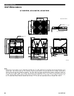
Page 26: ...the unit is no higher than on spring isolators Recommended minimum clearances Side to wall 6 rear to wall 6 control panel to end wall 4 0 top no obstructions allowed distance between adjacent units 1...

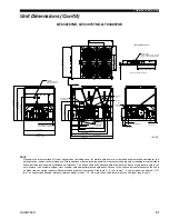
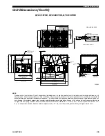
Page 27: ...50Hz OPTIONAL DISCONNECT SWITCH STANDARD ON CE 2077 81 8 82 3 2 51 4 2 02 1117 44 0 1678 66 1 1298mm EUROPEAN BUILD QTC3070TSE QTC3075TSE QTC3085TSE Unit Dimensions Cont d NOTE Placement on a level su...

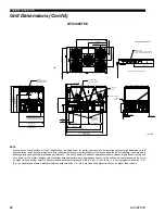
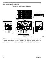
Page 28: ...NNECT SWITCH STANDARD ON CE 561 22 1 2795 110 0 1669 65 7 1132 44 6 573 22 5 2077 81 8 82 3 2 1298mm EUROPEAN BUILD 1177 46 4 QTC3095TSE Unit Dimensions Cont d NOTE Placement on a level surface of fre...

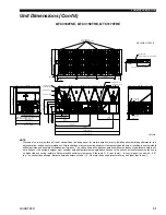
Page 29: ...2242 88 3 2254 88 8 1497mm 50Hz 1595 62 8 60Hz FRAME HEIGHT 2248 88 5 OVERALL HEIGHT DEPENDS ON BUILD LOCATION REFER TO NOTES 5 ADN 6 ABOVE 2077 81 8 82 3 2 83 3 3 Unit Dimensions Cont d NOTE Placeme...

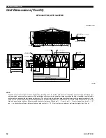
Page 30: ...C OUTLET 3 VICTAULIC INLET 2077 3 81 78 82 9 3 26 QTC3125TSE QTC3140TSE QTC3129THE Unit Dimensions Cont d NOTE Placement on a level surface of free of obstructions including snow for winter operation...

Page 31: ...78 82 4 3 24 ORIGIN 2169 2 85 40 36 4 1 43 15 9mm 5 8 DIA MOUNTING HOLES TYP QTC3160TSE QTC3150THE QTC3170THE Unit Dimensions Cont d NOTE Placement on a level surface of free of obstructions includin...

Page 32: ...end wall 4 0 top no obstructions allowed distance between adjacent units 10 No more than one adjacent wall may be higher than the unit 035 24059 017 REV LD26943 POWER ENTRY 330 2 13 00 WIDE X 177 8 7...

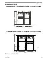
Page 33: ...1 4 FOUR FAN ISOLATOR LOCATIONS FOR QTC3070TSE QTC3075TSE QTC3085TSE All dimensions are inches unless otherwise specified Dimensions indicate isolator mounting centerlines LD18437 FOUR FAN ISOLATOR L...

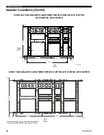
Page 34: ...R QTC3095TSE QTC3110TSE QTC3090THE QTC3100THE All dimensions are inches unless otherwise specified Dimensions indicate isolator mounting centerlines Isolator Locations Cont d LD18439 EIGHT FAN ISOLATO...

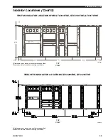
Page 35: ...l dimensions are inches unless otherwise specified Dimensions indicate isolator mounting centerlines Isolator Locations Cont d LD18441 TWELVE FAN ISOLATOR LOCATIONS QTC3205THE QTC3225THE LD21040 TOP V...

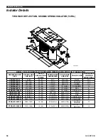
Page 36: ...2 GREEN 11 3 Y2RSI 2D 710 710 322 2 2 56 330 37 1072 486 DK BROWN 7 3 Y2RSI 2D 870 870 395 1 9 48 460 52 1312 595 RED 6 Y2RSI 2D 1200N 1200 544 1 9 48 638 72 1818 825 RED BLACK 4 3 Y2RSI 2D 1450 1450...

Page 37: ...20 120 54 1 2 30 DK YELLOW CP1 1D 175 175 79 1 17 30 DK BLUE CP1 1D 250 250 113 1 4 36 YELLOW CP1 1D 340 340 154 1 13 29 RED CP1 1D 510 510 231 1 02 26 BLACK CP1 1D 675 675 306 1 32 34 DK PURPLE CP1 1...

Page 38: ...500 680 0 5 12 40 RD4 BRICK RED WR 2250 1021 0 5 12 50 RD4 LIME WR 3000 1361 0 5 12 60 RD4 CHARCOAL WR 4000 1814 0 5 12 70 RD3 ISOLATORS ELASTOMERIC ISOLATOR LD17304 CD CD HF HF BT BT AL L AL L W W DW...

Page 39: ...ticle 440 22 5 Circuit breakers must be UL listed and CSA certified and maximum size is based on 225 of the rated load amps for the largest motor plus 100 of the rated load amps for all other loads in...

Page 40: ...UNTED CIRCUIT BREAKER FLA FULL LOAD AMPS HZ HERTZ MAX MAXIMUM MCA MINIMUM CIRCUIT AMPACITY MIN MINIMUM MIN NF MINIMUM NON FUSED RLA RATED LOAD AMPS S P WIRE SINGLE POINT WIRING UNIT MTD SERV SW UNIT M...

Page 41: ...0 9 22 6 6 18 2 5 5 14 6 4 4 I 5 1800 15 4 4 6 13 3 9 7 9 2 4 6 5 2 5 2 1 6 J 15 3600 43 12 9 36 4 10 9 22 6 6 18 2 5 5 14 6 4 4 K 20 3600 54 16 2 45 13 5 28 7 8 6 22 5 6 8 18 5 4 L 3 1800 9 5 2 9 8 2...

Page 42: ...50 500 230 60 2 6 500 2 250 500 3 2 0 400 2 3 0 250 1 250 500 380 60 1 6 500 2 3 0 250 1 250 500 1 6 350 460 60 1 6 500 1 6 350 1 6 350 575 60 1 6 500 1 6 350 1 6 350 QTC3079T 208 60 2 6 500 2 250 500...

Page 43: ...0 QTC3129T 208 60 3 2 0 400 3 2 0 400 2 250 500 3 2 0 400 2 250 500 230 60 3 2 0 400 3 2 0 400 2 250 500 3 2 0 400 2 250 500 380 60 2 6 500 2 250 500 3 2 0 400 2 250 500 3 2 0 400 460 60 2 6 500 1 250...

Page 44: ...2 4 19 575 60 137 150 150 150 21 5 132 21 5 132 21 5 132 2 2 9 15 3 85T 208 60 416 600 450 450 57 7 284 57 7 284 57 7 284 2 7 6 44 230 60 412 600 450 450 57 7 330 57 7 330 57 7 330 2 7 4 37 380 60 224...

Page 45: ...4 145 24 4 145 2 4 19 575 60 137 150 150 150 17 4 109 17 4 109 17 4 109 2 2 9 15 3 85T 208 60 416 600 450 450 57 7 284 57 7 284 57 7 284 2 7 6 44 230 60 412 600 450 450 57 7 330 57 7 330 57 7 330 2 7...

Page 46: ...2 578 6 7 4 37 380 60 383 400 400 400 64 3 355 64 3 355 64 3 355 6 4 5 23 1 460 60 319 400 350 350 53 1 290 53 1 290 53 1 290 6 4 19 575 60 252 400 300 300 42 5 255 42 5 255 42 5 255 6 2 9 15 3 160T 2...

Page 47: ...0 383 400 400 400 64 3 355 64 3 355 4 4 5 23 1 460 60 319 400 350 350 53 1 290 53 1 290 4 4 19 575 60 252 400 300 300 42 5 255 42 5 255 4 2 9 15 3 160T 208 60 740 800 800 800 106 2 523 106 2 523 106 2...

Page 48: ...QUANTECH FORM QTC3 EG6 1118 48 Wiring Diagram...

Page 49: ...FORM QTC3 EG6 1118 QUANTECH 49 LD18444 Wiring Diagram Cont d...

Page 50: ...ATER INTERNAL 120 VAC WIRING TO F1 FUSE INTERNAL 120 VAC WIRING TYPICALLY FROM CONTROL TRANSFORMER INTERNAL NEUTRAL WIRING INTERNAL NEUTRAL WIRING INTERNAL NEUTRAL WIRING TYPICALLY FROM CONTROL TRANSF...

Page 51: ...URE CUTOUT FSI FAN SPEED INHIBIT TWO SPEED XTBC TERMINAL BLOCK CUSTOMER Y R O T C A F K C O L B L A N I M R E T F B T X Y L N O N O I T P O N A F GND GROUND YHGSV HOT GAS SOLENOID VALVE G Y GREEN YELL...

Page 52: ...amage to the unit and its controls 1 Refer to installation commissioning operation and maintenance manual for customer connections and customer connection notes non compliance to these instructions wi...

Page 53: ...l condenser air flow Recommended clearances for units are given in the Unit Dimensions on page 26 When the available space is less the unit s must be equipped with the discharge pres sure transducer o...

Page 54: ...ice for more information about successfully applying QTC3 chillers CHILLED LIQUID PIPING The chilled liquid piping system should be laid out so that the circulating pump discharges into the evaporator...

Page 55: ...nce with applicable sections of the following Standards and Codes 1 AHRI 550 590 Water Chilling Packages Using the Vapor Compression Cycle 2 AHRI 370 Sound Rating of Large Outdoor Refrigerating and Ai...

Page 56: ...n of Refrigerants Chiller shall include not less than two refrigerant circuits above 50 tons 200kW scroll compressors direct expansion type evaporator air cooled condenser refrigerant lubrication syst...

Page 57: ...OMPONENTS Each refrigerant circuit shall include a discharge service ball type isolation valve high side pressure relief liquid line shutoff valve with charging port low side pressure relief de vice f...

Page 58: ...during fan cycling Guards of heavy gauge PVC polyvinyl chloride coated or galvanized steel shall be factory installed Option Ultra Quiet Fans 3 Fan Motors High efficiency direct drive 6 pole 3 phase...

Page 59: ...System Safeties in clude high discharge pressure low suction pressure high pressure switch and motor protector Compressor motor protector shall protect against damage due to high input current or ther...

Page 60: ...een the transformer and the control panel E Power Factor Correction Capacitors Provided to correct unit compressor factors to a 0 90 0 95 F Condenser Coil Environmental Protection 1 Post Coated Dipped...

Page 61: ...for mounting under the unit base rails 3 2 Deflection Restrained Spring Isolators level adjustable restrained mounts in rug ged welded steel housing with vertical and horizontal limit stops Housings s...

Page 62: ...Printed on recycled paper Form QTC3 EG6 1118 Supersedes QTC3 EG6 618 2018 P O Box 423 Milwaukee WI 53201 Printed in USA Issued on 11 30 18...

Reviews: