QUANTECH
52
FORM QWC4-NM1 (221)
ISSUE DATE: 02/28/2021
SECTION 3 - HANDLING, STORAGE, INSTALLATION, AND REASSEMBLY
PIPING CONNECTIONS
After the unit is leveled (and wedged in place for op-
tional spring isolators) the piping connections may be
fabricated. Arrange the piping with offsets for flexibil-
ity, and are adequately supported and braced indepen-
dently of the unit to avoid strain on the unit and vibra-
tion transmission. Hangers must allow for alignment of
pipe. Isolators (by others) in the piping and hangers are
highly desirable, and may be required per specifications.
CHECK FOR PIPING ALIGNMENT
When piping is complete, check for alignment. Open a
connection in each line, as close to the unit as possible,
by removing the flange bolts or coupling. If any bolt
is bound in its hole, or if the connection springs are
out of alignment, correct the misalignment by properly
supporting the piping or by applying heat to anneal the
pipe.
It may be necessary to weld chilled or condenser water
piping directly to the water pipe nozzles. Since chilled
and condenser water temperature sensor wells are of-
ten in close proximity to these connection points, sen-
sors in the wells may often see temperatures of several
hundred degrees, which can potentially damage them.
Establish a good clean welding ground connection near
the point of weld to prevent stray current from damag-
ing other sensors or chiller control wiring. Any damage
will likely show up as error in the sensor.
As a precautionary measure, remove the
sensors from the wells during the welding
process. If the sensor is removed, make sure
that it bottoms out when it is placed back in
the well.
If the piping is annealed to relieve stress,
clean the scale out of the pipe before it is
bolted in place.
CONDENSER AND CHILLED LIQUID
PIPING
General Requirements
The following piping recommendations are intended
to ensure satisfactory operation of the unit. Failure to
follow these recommendations could cause damage to
the unit, and may invalidate the warranty.
The maximum flow rate and pressure drop
for the condenser and evaporator must not
be exceeded at any time. The liquid must
enter the waterbox at the inlet connection,
which is typically the lower connection.
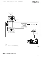
A flow switch must be installed in the
customer piping at the outlet of the cooler,
and the condenser and wired back to the
control panel, using shielded cable.
Arrange a straight run of piping of at least five pipe
diameters on either side of the flow switch. The chilled
liquid flow switch should be wired to Terminals 2 and
13 on the 1TB Terminal Block, and is required to pre-
vent damage to the cooler caused by the unit operating
without adequate liquid flow.
The condenser flow switch, which lets the chiller
shut down to avoid excess head until flow is restored,
should be wired to Terminals 2 and 12 on the 1TB Ter-
minal Block.
The flow switches must have gold plated contacts
for low voltage/current operation. Paddle type flow
switches suitable for 150 psig (10 kPa) working pres-
sure that have a one in NPT connection can be ob-
tained from Quantech as an accessory for the unit. Al-
ternatively, a differential pressure switch fitted across
an orifice plate may be used, preferably of the high/
low limit type.
The liquid pump installed in the piping systems should
discharge directly into the unit. The pumps may be
controlled by the chiller controls or external to the unit.
Piping and fittings immediately next to the chiller
should be readily demountable to enable cleaning be-
fore operation, and to facilitate visual inspection of the
exchanger nozzles.
The tubes must be protected by a strainer,
preferably 40 mesh, and must fit as close as
possible to the liquid inlet connection, and
be provided with a means of local isolation.
Summary of Contents for QWC4
Page 14: ...QUANTECH 14 FORM QWC4 NM1 221 ISSUE DATE 02 28 2021 THIS PAGE IS INTENTIONALLY LEFT BLANK...
Page 64: ...QUANTECH 64 FORM QWC4 NM1 221 ISSUE DATE 02 28 2021 THIS PAGE IS INTENTIONALLY LEFT BLANK...
Page 82: ...QUANTECH 82 FORM QWC4 NM1 221 ISSUE DATE 02 28 2021 THIS PAGE IS INTENTIONALLY LEFT BLANK...
Page 130: ...QUANTECH 130 FORM QWC4 NM1 221 ISSUE DATE 02 28 2021 THIS PAGE IS INTENTIONALLY LEFT BLANK...
Page 146: ...QUANTECH 146 FORM QWC4 NM1 221 ISSUE DATE 02 28 2021 THIS PAGE IS INTENTIONALLY LEFT BLANK...
Page 152: ...QUANTECH 152 FORM QWC4 NM1 221 ISSUE DATE 02 28 2021 THIS PAGE IS INTENTIONALLY LEFT BLANK...
Page 155: ...QUANTECH 155 NOTES...

