background image

QUANTECH

33

SECTION 3 - HANDLING, STORAGE, INSTALLATION, AND REASSEMBLY

FORM QWC4-NM1 (221) 

ISSUE DATE: 02/28/2021

3

Installing the Evaporator

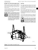
Use the following instructions to install the evaporator 

as shown in 

Figure 11 on page 33

.

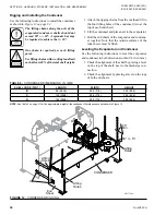
The lifting chains along the axis of the 

evaporator/condenser shells should not 

exceed 90° +/- 10°. A spreader bar may 

be required to achieve the +/- 10°.

One chain is required per each lifting 

point.
Use lifting chains with working load limit 

each at least 40% of the total shell weight.

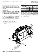
TABLE 5 - 

EVAPORATOR DIMENSIONS, IN. (MM)

SHELL CODE (PIN 5)

LENGTH

WIDTH

HEIGHT

B

96 (2438)

28.7 (729)

66.3 (1685)

C

120 (3048)

28.7 (729)

66.3 (1685)

D

144 (3658)

28.7 (729)

66.3 (1685)

NOTE: 

See 

Table 3 on page 31 

for the approximate weight and water capacity of the evaporator.

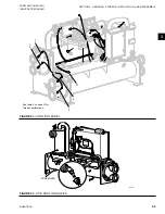
LD17751a

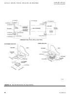
EVAPORATOR

Lifting

Holes

90° +/- 10˚

65° 

Min.

Lifting

Holes

Lifting

Holes

FIGURE 11 - 

RIGGING THE EVAPORATOR

1.  Attach the rigging chains from the overhead lift to 

the four lifting holes of the evaporator (two at the 

top of each end sheet).

2.  Lift the evaporator by means of an overhead lift to 

the unit's final location on the floor or housekeep

-

ing pad

.

For information about clearance requirements, see 

Ta-

ble 2 on page 28

.

Summary of Contents for QWC4

Page 1: ...DEL QWC4 SINGLE COMPRESSOR 60 HZ 120 TONS TO 200 TONS WATER COOLED SCREW LIQUID CHILLERS INSTALLATION OPERATION MAINTENANCE New Release Form QWC4 NM1 221 Issue Date February 28 2021 035 28391 000 R 13...

Page 2: ...abels this document and any referenced materials This in dividual shall also be familiar with and comply with all applicable industry and governmental standards and regulations pertaining to the task...

Page 3: ...te or provide current information automatically to the manual or product owner Updated manuals if applicable can be obtained by contacting the nearest Quantech Service office or accessing the Johnson...

Page 4: ...45 mm GX 1 151 mm EE 2 136 136 mm FE 2 145 136 mm FF 2 145 145 mm EE PASS A Evap 1 pass Cond 1 pass B Evap 2 pass Cond 1 pass C Evap 3 pass Cond 1 pass D Evap 1 pass Cond 2 pass E Evap 2 pass Cond 2 p...

Page 5: ...ON 3 HANDLING STORAGE INSTALLATION AND REASSEMBLY 23 Shipment and Storage 23 Inspection Damage and Shortage 25 Lifting Weights 26 Moving the Chiller for Forms 1 and 2 27 Foundation 28 Clearance for Se...

Page 6: ...nce 84 User Interface 88 Fault Messages 91 Microboard 331 03478 xxx 91 Program Update 93 Data Logging 94 Acceptable Printers 123 Printer Connections 123 Printer Setup 123 Printing a Report 124 BAS Com...

Page 7: ...DATE 02 28 2021 TABLE OF CONTENTS CONT D SECTION 8 TROUBLESHOOTING 147 Abnormal Operation Analysis and Correction 147 Troubleshooting the Compressor and Oil Separation System 147 SECTION 9 DECOMMISSI...

Page 8: ...trol Panel 45 FIGURE 24 VSD Cooling Hoses 45 FIGURE 25 Alternate Piping for VSD 46 FIGURE 26 Torque Pattern 47 FIGURE 27 Adjustable End Fitting 48 FIGURE 28 Back Off Locknut 49 FIGURE 29 Screw Fitting...

Page 9: ...59 Printer Cable Connection from QWC4 Chiller to a Computer 122 FIGURE 60 Printer Cable Connection from QWC4 Chiller to a Serial Printer 123 FIGURE 61 Sample Printout 125 FIGURE 62 System Switches and...

Page 10: ...Pin 22 Power Field 63 TABLE 22 Lug Data GB Pin 22 Power Field 63 TABLE 23 Voltage Variations 63 TABLE 24 Complete Pin Number Description 65 TABLE 25 Evaporator Nozzle Dimensions in mm 74 TABLE 26 Cond...

Page 11: ...edure Refer to Limited Warranty Form 50 05 NM2 Quantech warrants all equipment and materials against defects in workmanship and materials for a period of 18 months from the date of shipment or 12 mont...

Page 12: ...nal safety the safety of other personnel and the equipment Correct utilization of the equipment in accordance with the procedures detailed in the manual MISUSE OF EQUIPMENT Suitability For Application...

Page 13: ...when working on the unit The buildup of refrigerant vapor from a leak for example does pose a risk of as phyxiation in confined or enclosed spaces and attention should be given to good ventilation Us...

Page 14: ...QUANTECH 14 FORM QWC4 NM1 221 ISSUE DATE 02 28 2021 THIS PAGE IS INTENTIONALLY LEFT BLANK...

Page 15: ...5 opto coupled data link The VSD logic board runs the compressor to the speed requested by the chiller microprocessor to meet the load as shown in Figure 4 on page 18 Quantech QWC4 chillers are design...

Page 16: ...8 2021 SECTION 2 PRODUCT DESCRIPTION Figure 2 QWC4 CHILLER MAJOR COMPONENTS FRONT VIEW LD17364 1 Control Panel 2 Variable Speed Drive VSD 3 Oil Separator 4 Return Waterbox 5 Condenser 6 Condenser Sigh...

Page 17: ...RM QWC4 NM1 221 ISSUE DATE 02 28 2021 2 Figure 3 QWC4 CHILLER MAJOR COMPONENTS REAR VIEW LD17365 1 VSD 2 Compressor 3 Evaporator Sight Glass 4 Evaporator Water Nozzle 5 Liquid Level Sensor 6 Liquid Li...

Page 18: ...T LD15028 INPUTS Pressure Transducers Temperature Sensors Switches Liquid Flow High Pressure Start Stop Level Customer Supplied Contacts CONTROL PANEL Chiller Control Board Microprocessor User Interfa...

Page 19: ...panel meters some refrigerant gas to the com pressor to reduce energy consumption COMPLETE FACTORY PACKAGE Each unit is shipped as a complete factory package completely assembled with all interconnec...

Page 20: ...each compressor to keep the leaving water tempera ture at the setpoint The control system logic monitors the rate at which the leaving water temperature is approaching the setpoint to ramp up or down...

Page 21: ...wo safety relief valves are mounted in parallel one valve is always operational to assist in valve replace ment during maintenance Electrical Isolation Circuit Breaker UL ASME A unit mounted cir cuit...

Page 22: ...uate head pressure exists SECTION 2 PRODUCT DESCRIPTION The preferred means is cooling tower bypass circuit since this would maintain adequate tube velocity in the condenser by regulating the return c...

Page 23: ...ability all units are tested and inspected before leaving the fac tory The chiller may be ordered and shipped in any of the following forms Form 1 shipped assembled with refrigerant charge Form 2 ship...

Page 24: ...removed from the shells and skidded separately Form 7 QWC4 chillers are shipped in the following as semblies The driveline compressor motor assembly Evaporator Condenser Variable Speed Drive VSD Contr...

Page 25: ...he assemblies all containers should be opened and contents checked against the packing list Any material shortage should be reported to Quan tech immediately Refer to Shipping Damage Claims Form 50 15...

Page 26: ...TOR MIN MAX LB KG LB KG LB KG LB KG FX B B 7694 8329 3490 3778 8254 8995 3744 4080 276 298 125 135 2064 2249 936 1020 C C 8263 8519 3748 3864 8915 9306 4044 4221 331 353 150 160 2229 2326 1011 1055 D...

Page 27: ...t in death or serious injury or possible equipment or property only damage RIGGING The complete standard unit Forms 1 and 2 is shipped without skids When optional skids are used it may be necessary to...

Page 28: ...apable of supporting the unit operating weight CLEARANCE FOR SERVICE To ensure adequate space for servicing the unit adhere to the following clearances as shown in Figure 8 on page 28 for single and d...

Page 29: ...of the shell end sheets at each end of the unit The unit should be level within 0 25 in 6 mm from one end to the other end and from front to the rear If the chiller is not level within the amount spe...

Page 30: ...and transversely If the leveling bolts are not long enough to level unit due to an uneven or sloping floor or foundation add as many shims as neces sary grouted if necessary under the isolator 4 Afte...

Page 31: ...nstall oil supply piping see Figure 21 on page 42 14 Mount the VSD see Figure 22 on page 44 15 Connect the VSD cooling lines see Figure 24 on page 45 16 Mount and connect the Control Panel see Figure...

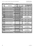
Page 32: ...on page 47 for Torque Specifications 94 Tee UNF F 0 750in UNF F 0 750in UNF 023 25549 000 827494 J 31 Elbow 1 2 O D Tube 90 Deg Male 023 18982 000 146248 OIL SEPARATOR MOUNTING P 18 HCS5 0 375 16 X 2...

Page 33: ...shell weight Table 5 EVAPORATOR DIMENSIONS IN MM SHELL CODE PIN 5 LENGTH WIDTH HEIGHT B 96 2438 28 7 729 66 3 1685 C 120 3048 28 7 729 66 3 1685 D 144 3658 28 7 729 66 3 1685 NOTE See Table 3 on page...

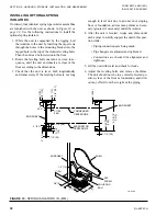
Page 34: ...next to the evaporator 3 Bolt the end sheets of the evaporator and condens er together Note that the outside surfaces of the tube sheets must be flush Leveling the Evaporator and Condenser Use the fo...

Page 35: ...total shell weight 2 With an adequate lifting device lift the unit slight ly off the ground to determine adjustments neces sary to keep the unit level Make adjustments as necessary to level the unit...

Page 36: ...QUANTECH 36 FORM QWC4 NM1 221 ISSUE DATE 02 28 2021 SECTION 3 HANDLING STORAGE INSTALLATION AND REASSEMBLY FIGURE 12 ISOLATOR INSTALLATION CONT D LD16471...

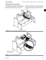
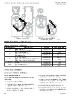
Page 37: ...pecifications LD17755 B Figure 15 HEAT EXCHANGER PIPES Installing the Heat Exchanger Piping Use the following instructions after the temporary ship ping brackets supporting the heat exchanger piping h...

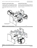
Page 38: ...iping on each side of the chiller using the proper o rings and hardware as shown in Figure 16 on page 38 See Table 4 on page 32 for Torque Specifications LD17756 K L Figure 16 LIQUID INJECTION PIPING...

Page 39: ...ighten the bolts until all con nections are made to the compressor Specific shim pads will be bolted to the compressor supports to satisfy the align ment between the compressor and system piping Insta...

Page 40: ...19 on page 41 1 Lift the line with muffler and remove the pack ing materials Clean all sealing surfaces 2 Bolt the line to the flange on the oil separator and to compressor discharge using the proper...

Page 41: ...GE INSTALLATION AND REASSEMBLY FORM QWC4 NM1 221 ISSUE DATE 02 28 2021 3 See Table 4 on page 32 for Torque Specifications LD17759 With Isolation Ball Valve E F P E R R Figure 19 OIL SEPARATOR DISCHARG...

Page 42: ...6 145 Compressor Ports J Oil Return from Oil Separator H Oil Return from Eductor J Oil Return from Oil Separator H Oil Return from Eductor Oil Pressure Transducer Oil Pressure Transducer 151 Compresso...

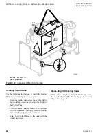
Page 43: ...the condenser Carefully lower the VSD onto the sup port on the condenser Use a spreader bar to ensure that the lift ing chains do not bend the lifting tongs on the VSD 3 Install the VSD to the plate w...

Page 44: ...own in Figure 23 on page 45 1 Attach the rigging chains from the overhead lift to the two lifting holes one at the top of each end of the Control Panel 2 Lift the Control Panel by means of an overhead...

Page 45: ...RAGE INSTALLATION AND REASSEMBLY FORM QWC4 NM1 221 ISSUE DATE 02 28 2021 3 See Table 4 on page 32 for Torque Specifications LD17764 1 4 1 4 1 4 1 4 51 5 Detail A 14 Figure 23 CONTROL PANEL LD17763 CON...

Page 46: ...THREAD JOINTS Use the following information to add primer to the pipe thread joints 1 Use primer with dissimilar metals 2 Use primer on both male and female components of pipe threads 3 in 25 mm and...

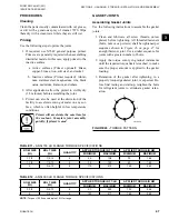
Page 47: ...mbling Gasket Joints Use the following instructions to assemble the gasket joints 1 Clean and lubricate all screw threads unless plated before tightening All threaded fasteners bolts nuts or cap screw...

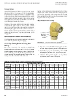
Page 48: ...d wiched between the angular sealing surface of the fe male port and the shoulder of the male end Sealing is thus affected and maintained by the O ring compression which results from the clamping forc...

Page 49: ...achine threads beyond the fitting land area during step 7 6 Using two wrenches hold fitting in required posi tion and tighten locknut to the appropriate torque value shown in Table 14 on page 50 or Ta...

Page 50: ...of synthetic Polyolester POE oil or POE grease 4 Thread the nut by hand and tighten nut to the ap propriate torque value shown in Table 14 on page 50 or Table 15 on page 51 Table 14 ASSEMBLY TORQUE ME...

Page 51: ...12 UN2A 028 12961 019 180 2 1 4 12 028 12961 036 225 Table 16 BRAZED JOINTS ACTUAL O D TUBE SIZE IN MALE END FEMALE END OUTSIDE DIAMETER A IN LENGTH K IN INSIDE DIAMETER F IN DEPTH G IN MINIMUM MAXIMU...

Page 52: ...D PIPING General Requirements The following piping recommendations are intended to ensure satisfactory operation of the unit Failure to follow these recommendations could cause damage to the unit and...

Page 53: ...f peak seasons of the year QWC4 chill ers can be operated with entering condensing water temperature that is less than design conditions Operating the chiller below its minimum ECW could result in low...

Page 54: ...meet high leaving liquid tem perature requirements PIPEWORK ARRANGEMENT Piping arrangement vary according to design and facil ity application Figure 33 on page 54 is a suggested piping arrangement fo...

Page 55: ...d adapters are supplied loose The flange dimensions are to ISO 7005 NP10 LD29433 WELD FLANGE GROOVED ADAPTER Figure 36 FLANGE ATTACHMENT REFRIGERANT RELIEF PIPING In case of an emergency each unit is...

Page 56: ...ER VALVE COMPONENT DESIGN PRESSURE PSIG BAR AIRFLOW CAPACITY LB MIN KG S OUTLET CONNECTION EVAPORATOR 235 16 2 55 9 0 423 1 in NPTF CONDENSER 235 16 2 55 9 0 423 1 in NPTF CONDENSER HEAT PUMP OPTION 3...

Page 57: ...ming the 3 phase power supply must enter via the same cable entry All sources of supply to the unit must be taken via a common point of isolation not supplied by Quantech Use copper power wiring only...

Page 58: ...ow which will cause evaporator freeze up if the chiller is permitted to run Condenser Liquid Flow Switch This switch is expected across Terminals 2 and 12 of 1TB to indicate loss of liquid flow which...

Page 59: ...t pump option is in stalled The function of the input is controlled by se lecting the operating mode described in SECTION 6 OPERATION in this manual Current Limit Reset Control Install input for Curre...

Page 60: ...s a motor winding short 5 Connect the following system inputs to their re spective terminals of 1TB Terminal Box a Chilled Liquid Flow Switch Terminals 2 and 13 b Condenser Liquid Flow Switch Terminal...

Page 61: ...ct we are requesting the presence of your Quantech Authorized Representative at the job site on ______ ______ ______ to start the system and instruct operating personnel Have the Quantech representati...

Page 62: ...ION AND REASSEMBLY Figure 38 POWER CONNECTIONS VSD CONTROL PANEL STANDARD CONTROL TRANSFORMER UNIT CONTROLS PE LINE REACTOR CIRCUIT BREAKER OPTION AVAILABLE FIELD PROVIDED UNIT POWER SUPPLY SEE NOTE 1...

Page 63: ...E RANGE LUG PHASE WIRES PER LUG LUG WIRE RANGE LUG PHASE WIRES PER LUG LUG WIRE RANGE J 380 60 1 2 2 AWG 600 kcmil 1 2 1 0 AWG 500 kcmil 1 2 2 AWG 600 kcmil 460 60 1 2 2 AWG 600 kcmil 1 2 1 0 AWG 500...

Page 64: ...QUANTECH 64 FORM QWC4 NM1 221 ISSUE DATE 02 28 2021 THIS PAGE IS INTENTIONALLY LEFT BLANK...

Page 65: ...ize L 12 PASS ARRANGEMENT A Evap 1pass Cond 1pass B Evap 2pass Cond 1pass C Evap 3pass Cond 1pass D Evap 1pass Cond 2pass E Evap 2pass Cond 2pass F Evap 3pass Cond 2pass G Evap 1pass Cond 3pass H Evap...

Page 66: ...AND VSD ENCLOSURE TYPE S Ctrl VSD N1 IP20 AT N1 IP20 E Ctrl VSD IP33 Q Special Quote 26 UNIT NEMA TYPE S UNIT NEMA1 OR IP20 Q Special Quote 27 VSD COOLING SOURCE X No selection S Condenser liquid H Ev...

Page 67: ...Condenser isolation valves Q Special Quote 39 HOT GAS BYPASS X No Selection Q Special Quote 40 LIQUID INJECTION KIT X No Selection L Liquid injection kit Q Special Quote 41 REFRIGERANT A R 134a 42 COM...

Page 68: ...G WATER TEMP LCHWT Temperature QQ Special Quote 54 56 EVAPORATOR TUBE TYPE 321 0 75 in x 0 025 in Wall 322 0 75 in x 0 028 in Wall 323 0 75 in x 0 035 in Wall QQQ Special Quote 57 EVAPORATOR WATERBOX...

Page 69: ...opper Nickel 260 0 75 in x 0 025 in Copper 261 0 75 in x 0 028 in Copper 262 0 75 in x 0 035 in Copper 162 0 75 in x 0 028 in Titanium QQQ Special Quote 70 CONDENSER WATERBOX TYPE C Compact M Marine 7...

Page 70: ...astomeric pad I 1 inch deflection spring isol F Feet without elastomeric pad Q Special Quote 80 PAINT OPTIONS S Caribbean Blue Q Special Quote 81 STRUCTURAL MODIFICATION X No Selection Q Special Quote...

Page 71: ...se vacuum test doc A Wuxi all document Q Special Quote 87 FACTORY TESTS X No Factory Tests F Function witness incl ctrl P Perf test without witness W Customer perf witness test T Tube side hydrostatic...

Page 72: ...4 NM1 221 ISSUE DATE 02 28 2021 SECTION 4 TECHNICAL DATA SINGLE COMPRESSOR UNIT DIMENSIONS Figure 39 SINGLE COMPRESSOR UNIT DIMENSIONS LD16476a LD16476b LD16476d N M F G P B D E C I H A J K TOP VIEW S...

Page 73: ...2 PASS 3 PASS 1 PASS 2 PASS 3 PASS H 1 1 17 32 344 1 1 17 32 344 1 1 17 32 344 14 1 2 369 14 1 2 369 14 1 2 369 I 1 2 3 8 369 1 2 3 8 369 16 3 32 409 16 3 32 409 DIM REAR HEAD 2 PASS REAR HEAD 2 PASS...

Page 74: ...ERBOXES 2 PASS NOZZLE ARRANGEMENTS NUMBER OF PASSES EVAPORATOR PIN 5 6 IN OUT 3 G N P F Figure 41 EVAPORATORS COMPACT WATERBOXES 3 PASS Table 24 EVAPORATOR NOZZLE DIMENSIONS IN MM EVAPORATOR SHELL COD...

Page 75: ...IN 7 NOZZLE PIPE SIZE CONDENSER NOZZLE DIMENSIONS ft in mm NO OF PASSES 1 PASS 2 PASS 3 PASS 1 2 3 CC GG BB DD GG BB DD GG B C D 8 5 5 127 1 2 13 32 366 1 1 15 32 366 8 11 16 366 1 8 1 8 366 1 1 11 32...

Page 76: ...890 56 150 9 590 37 CD 330 21 910 57 220 14 660 42 CD 480 30 1950 123 240 15 910 57 DB 240 15 750 47 160 10 490 31 DB 390 25 1560 98 190 12 780 49 130 8 520 33 DC 280 18 870 55 190 12 570 36 DC 440 28...

Page 77: ...he evap orator and condenser Evacuation and charging should always be done according to SECTION 7 MAINTENANCE Service and Oil Line Valves If valves are of the back seat type open them fully counterclo...

Page 78: ...erminals 11 If the VSD provides an optional circuit break er at the incoming power connection to the VSD make sure the settings are prop erly set per the information on the next page 12 Find your VSD...

Page 79: ...ied individuals are permit ted to service this product and are to be knowledgeable of and adhere to all safe work practices as required by local codes Use proper personal protection where and when req...

Page 80: ...er adverse conditions develop Continued on following page Programmed Options Program the required options in the control panel for the desired operating requirements then record the values be low Refe...

Page 81: ...ompressor which does not develop oil pressure immediately Switch the UNIT switch to the OFF position 10 Adjust condenser refrigerant liquid level setpoint to a value that covers the subcooler top and...

Page 82: ...QUANTECH 82 FORM QWC4 NM1 221 ISSUE DATE 02 28 2021 THIS PAGE IS INTENTIONALLY LEFT BLANK...

Page 83: ...d right side of the keypad Displays Program setpoints History data and To initiate system commands Use the following keys in the center to enter data in the various program modes 0 9 is a NUMERIC KEYP...

Page 84: ...isplaying unit system parameters and operator messages The display has an LED backlight for night viewing and is viewable in direct sunlight BASIC OPERATING SEQUENCE Start Sequence and Loading To star...

Page 85: ...ressor is shut off Chilled and Condenser Liquid Flow Switches The chilled and condenser liquid flow switches must have electrical continuity to Terminal 2 to permit the chiller to run Remote Run Permi...

Page 86: ...the local setpoint A full scale signal input 100 equates to a posi tive offset to the local setpoint equal to the pro grammable maximum REMOTE TEMP RESET The offset is linear and may be adjusted betw...

Page 87: ...m the factory Remote BAS Comms Reset Set the LCLT setpoint via the BAS COMMS The control panel will only accept a remote setpoint from the BAS if the control panel is in REMOTE CONTROL MODE under the...

Page 88: ...lue of the REMOTE INPUTS SERVICE TIME as programmable under the UNIT SETUP MODE at the factory for the default value of 15 minutes The low limit is five minutes and the high limit is 60 minutes The re...

Page 89: ...ning There is a one second delay until the unit shuts down General or fault status External device and unit system switches status Load limiting The display will show the highest priority message as d...

Page 90: ...TUS CONDENSER LIQUID FLOW SWITCH SHUTDOWN The flow switch is open which is preventing the unit from running There is a one second delay until the unit shuts down UNIT STATUS VSD COOLING SHUTDOWN The c...

Page 91: ...ash memory instead of EPROM Program updates are accomplished by load ing the new program from an SD card inserted into the SD card reader writer This same SD card reader writer also allows the user to...

Page 92: ...ioning the power supply test points should be measured to deter mine the status of the microboard Power Supply Test Points TP1 GND Measure TP2 TP3 TP4 and TP5 in refer ence to this Test Point TP2 3 3...

Page 93: ...this case the existing data base will be used with the new software The database cannot be updated without updating the software To update the Program 1 Copy the new software in to the root directory...

Page 94: ...ed that will hold less data but should be tested for compatibility The controller operating system does not support SD cards larger than 2GB When the SD card becomes full the oldest date file is autom...

Page 95: ...which indicates an invalid letter or number exists in a location in the serial number string the chiller may have lost important factory programmed information Contact Quantech Product Technical Suppo...

Page 96: ...he VSD logic board This data is stored in the board battery backed RAM for safekeep ing and is transferred to the panel via the communica tions link First Fault Code The first fault code will be set f...

Page 97: ...D cooling fan and water pump will remain energized until the internal temperature drops below 148 F 64 4 C at which time the unit will be allowed to restart The VSD cooling fan and water pump are de e...

Page 98: ...ramped shutdown if the control board loses communications with the VSD logic board while the chiller is operating On power up the microprocessor board will attempt to initialize communications with t...

Page 99: ...using the keypad YYYYYYY GATE DRIVER FAULT Hardware Initiated Fault The VSD IGBT gate driver control board monitors the saturation voltage drop across each IGBT while it commands it gated on If the I...

Page 100: ...626 amps min 674 amps max and 380V 50 60 Hz and 400 415 V 50 Hz VSD Frames C and D and 460V 60 Hz Frame D shutdown is 863 3 amps 831 amps min 896 amps max This auto restart safety will lock out on the...

Page 101: ...s 9 5 s or 100 Hz 60 s Current freq 5 Hz 10 Hz s NOTE 9 5 s 100 Hz 5 Hz 10 Hz s the time it takes to ramp from 100 Hz to 5 Hz After the timer expires the fault is linearly ramped from 0 psid 0 kPa to...

Page 102: ...e operator clears the fault using the keypad YYYYYYY LOW EVAP PRESS LCHLT This safety fault causes a lockout on the first fault and is bypassed for the first 10 minutes of chiller run time It is set i...

Page 103: ...sor to the compressor s 105 FLA ADJUST overload potentiometer setting If the current exceeds the setting continuously for 20 seconds the compressor will shut down This safety will lockout a system on...

Page 104: ...ws the rate of change of the chilled liquid temperature UNIT LEAD SYSTEM NUMBER 1 OR 2 UNIT CHILLED LIQUID FLOW SW ON OR OFF CONDENSER LIQUID FLOW SW ON OR OFF UNIT EVAP COND PUMP RUN ON OR OFF VSD CO...

Page 105: ...STEM DATA KEY Figure 50 SYSTEM DATA KEY SYSTEM DATA KEY System Data Key Operation The SYSTEM DATA key gives access to SYSTEM operating parameters The following list shows the data in the order in whic...

Page 106: ...0 F 150 C Discharge Temp 50 K Thermistor 40 3 F 4 61 C 302 0 F 150 C Evaporator Temp 3 K Thermistor 4 87 F 20 3 C 158 34 F 70 2 C Subcooled Liquid Refrig Temp 3 K Thermistor 18 83 F 7 31 C 175 61 F 7...

Page 107: ...s as set under the PROGRAM key remotely by a BAS and REMOTE CURRENT LIMIT input Inactive current limits will display XX instead of a numeric value VSD DC BUS VOLTAGE VDC VSD INTERNAL AMBIENT TEMP F CO...

Page 108: ...The list below explains the configurations is the FAULT HISTORY number YYY is the ALL FAULT description ZZ is the ALL FAULT number WW is the total number of ALL FAULTS for the current history To acces...

Page 109: ...7 Day of Week Day of Month etc OPTIONS on page 118 Display Language Liquid Type etc PROGRAM on page 112 Chilled Liquid Leaving Temp Cutout Motor Current Limit etc See the specific section of this manu...

Page 110: ...mote setpoint or range these values will display as SETPOINTS DEF LO HI MAX REMOTE HEATING TEMP RESET F Minimum maximum and default values allowed are listed in Table 37 on page 111 Press the SETPOINT...

Page 111: ...fines how far above and below the LCHLT setpoint the chiller will stop compressors or the entire unit and restart them to maintain LCHLT within the range The programmable CR defines the setpoint high...

Page 112: ...P XX X SEC PROGRAM DEF 50 LO 10 HI 1000 HPC TI XX X SEC PROGRAM DEF 0 LO 0 HI 60 HPC TD XX X SEC Press the PROGRAM key to modify the following nu meric operating parameters which are displayed when th...

Page 113: ...d 4245 and pressing ENTER key PROGRAM HPC DIRECTION XXXXXXXXXXXXXXXXXXXXXXXXXXXX PROGRAM DEF 0 0 LO 0 0 HI 100 0 HPC MINIMUM POSITION XX X Table 37 PROGRAM LIMITS PROGRAM VALUE MODE LOW LIMIT HIGH LIM...

Page 114: ...DEADBAND F SETUP MODE DEF 24 0 LO 2 0 HI 40 0 VI DIFF TEMP OFFSET F SETUP MODE DEF 50 0 LO 50 0 HI 95 0 MIN VSD FREQ SETP HZ SETUP MODE DEF 50 0 LO 50 0 HI 95 0 MIN START FREQ SETP HZ SETUP MODE DEF...

Page 115: ...5 HI 50 COND VLV STARTUP POS SETUP MODE DEF 5 LO 0 HI 10 COND VLV CTRL START DLY MIN SETUP MODE REFRIG INJ ENABLED SETUP MODE VI STEP VALVE ENABLED SETUP MODE DEF 195 0 LO 195 0 HI 333 0 HIGH DISCHAR...

Page 116: ...System Low Differential Oil Pressure Setpoint 20 psid 1 37 bard 60 psid 4 14 bard 30 psid 2 07 bard System Low Economizer Superheat 0 0 F 0 0 C 20 0 F 11 1 C 5 0 F 2 8 C Min Oil Pump Diff Setpoint 20...

Page 117: ...l Control Valve Startup Position 5 50 30 Condenser Level Control Startup Delay 0 min 10 min 5 min Condenser Level Ramp Up Time 0 min 10 min 5 min Refrigerant Injection DISABLED ENABLED DISABLED VI Ste...

Page 118: ...rench Italian German Spanish Portuguese Polish or Hungarian default is English OPTIONS LIQUID TYPE WATER OR GLYCOL COOLING OPTIONS LOCAL REMOTE CONTROL MODE LOCAL OR REMOTE CONTROL OPTIONS DISPLAY UNI...

Page 119: ...TIONS REMOTE CURRENT LIMIT INPUT 2 0 TO 10 VOLTS DC OPTIONS REMOTE CURRENT LIMIT INPUT 0 0 TO 20 0 MILLIAMPS OPTIONS REMOTE CURRENT LIMIT INPUT 4 0 TO 20 0 MILLIAMPS OPTIONS COMPRESSOR SELECT WITHOUT...

Page 120: ...e numeric keypad Once the correct values for the START hour and minute are entered press the key The cursor will move to the AM PM selection Change the meridian AM PM value with the or key and enter b...

Page 121: ...e first display reads SCHEDULE UNIT OPERATING S M T W T F S HOLIDAY NOTED BY Set the holiday times using the same procedure de scribed for the days of the week Press the key after setting the HOL STAR...

Page 122: ...LLER TO A COMPUTER MANUAL OVERRIDE If this key is pressed during a scheduled shutdown the STATUS key will display MANUAL OVERRIDE which indicates that the DAILY SCHEDULE is being ignored and the chill...

Page 123: ...lines if an unlisted printer is selected 1 All printers must be capable of RS 232 serial communications 2 The primary differences between printers involve the formatting control codes required by the...

Page 124: ...he or key until the required printout is displayed The available printout types are listed in Table 41 on page 124 Table 40 PRINTOUT TYPES PRINTOUT TYPES Operating Data Default All History Buffers Nor...

Page 125: ...REMOTE CONTROL NONE OPERATING HOURS 1 XXXXX 2 XXXXX Figure 61 SAMPLE PRINTOUT START COUNTER 1 XXXXX 2 XXXXX SOFTWARE VERSION C WCS 30 00 UNIT SERIAL NUMBER YYYY XXXZZZ VSD DATA ACTUAL FREQUENCY XXX X...

Page 126: ...operating conditions at the time of the fault regardless if a lockout occurred Whenever any fault occurs all system operating data is stored in battery backed memory on the control board at the insta...

Page 127: ...he pro grammable values that the user should never change They will be programmed at the factory or by qualified service personnel SYSTEM SWITCHES ON OFF RESET ON OR OFF OR RESET Use the SYSTEM SWITCH...

Page 128: ...After receiving a valid transmission from the E Link Gateway the unit will transmit operational data or his tory buffer data depending on the HISTORY BUF FER REQUEST Data must be transmitted for every...

Page 129: ...0 ALL OK 1 DATUM TYPE OK TEST FAILED 2 ENGLISH TEXT TOO LONG 3 FLOATING POINT EXCEPTION 4 GET PACKET FAILED 5 GET TYPE FAILED 6 INVALID UNIT CONVERSION 7 INVALID HARDWARE SELECTION 8 REAL TIME FAULT 9...

Page 130: ...QUANTECH 130 FORM QWC4 NM1 221 ISSUE DATE 02 28 2021 THIS PAGE IS INTENTIONALLY LEFT BLANK...

Page 131: ...s resistance X Clean or back flush VSD heat exchanger X Replace VSD coolant after cleaning heat exchanger X Perform oil analysis on compressor lube oil X Perform refrigerant analysis X Perform Eddy cu...

Page 132: ...r the oil level to be at the bottom of the lower sight glass or near the top of the upper sight glass on the oil separator depending on conditions Do not add oil unless the oil level cannot be seen in...

Page 133: ...r sight glass Start the chiller and run a load condition between 65 and 80 FLA for a minimum of one hour and then observe the oil level The oil level should become visible in either the lower or upper...

Page 134: ...wn in Figure 64 on page 134 3 Open the oil charging valve and pump oil into the system until the oil level in the oil separator is about midway in the upper sight glass and then close the charging val...

Page 135: ...emove the six cap screws that secure the oil filter cover to the compressor housing as shown in Fig ure 65 on page 135 5 Remove the oil filter housing cover and O ring seal 6 Remove the oil filter Exa...

Page 136: ...it able refrigerant recovery container Filter drier item 2 contains a Schraeder valve for this pur pose 5 Loosen the roto lock nut item 4 at the piping end of the filter drier item 2 6 Remove the filt...

Page 137: ...lare Purge air and non condensables from the charg ing hose Add only new refrigerant or refrigerant that has been tested and certified to meet American Refrig eration Institute Standard ARI 700 HANDLI...

Page 138: ...lve piping and evapora tor and condenser tube rolled joints PRESSURE CONNECTIONS All threaded pressure connections used on the QWC4 chillers are SAE straight thread O ring face seal fit tings or Primo...

Page 139: ...f the leaky tubes has been deter mined treat that section in the following manner if the location is not definite investigate all of the tubes 2 Wash off both tube heads and the ends of all tubes with...

Page 140: ...the system reacts like refrigerant Pulling down the pressure in the system where its saturation temperature is below room temperature heat will flow from the room through the walls of the system and...

Page 141: ...uation The small amount of moisture left will be carried out through the vacuum pump and the temperature or pres sure shown by the indicator should drop uniformly un til it reaches a temperature of 35...

Page 142: ...is located in an unheated area susceptible to freezing drain the wa ter from the condenser and evaporator to prevent the tubes from freezing Condenser Tubes Proper condenser water treatment can elimin...

Page 143: ...e the scale and dirt Contact a Quantech Field Service Office for a recom mended method that is used locally Chemical Cleaning Procedure Acid Cleaning of Tubes If the tubes are fouled with a hard scale...

Page 144: ...after a new filter element is installed contact a Quan tech Field Service Office ELECTRICAL CONTROLS For information covering the control center opera tion see SECTION 6 OPERATION in this manual and...

Page 145: ...PERATION 8 Add new coolant if necessary 9 Reinstall the cap before stopping the coolant pump to avoid overflowing the fill tube when the coolant pump is turned off The coolant system holds about 2 gal...

Page 146: ...QUANTECH 146 FORM QWC4 NM1 221 ISSUE DATE 02 28 2021 THIS PAGE IS INTENTIONALLY LEFT BLANK...

Page 147: ...ubleshooting the compressor is limited to iden tifying the probable cause If a mechanical problem is suspected contact the Quantech Field Service Office DO NOT DISASSEMBLE THE COM PRESSOR The VSD cont...

Page 148: ...sensor is defective Check sensor Condenser tubes are dirty or scaled Check and clean tubes Check water conditioning Condenser water flow low Check site pumps valves and strainers Increase quantity of...

Page 149: ...compressor heater Replace compressor heater System Fault Oil Pressure Gradually Decreases Oil filter is dirty Change oil filter Extreme bearing wear Call Quantech Field Service Office to evaluate com...

Page 150: ...TE Leaving Entering Condenser Liquid Temperature Sensor Subcooled Liquid Refrigerant Temperature Sensor Eductor Temperature Sensor Economizer Outlet Temperature Sensor Table 47 3K TEMPERATURE SENSOR E...

Page 151: ...95 225 2 75 50 2 1 50 1 23 230 3 85 50 1 230 2 8 55 2 26 55 1 3 235 3 92 55 1 05 235 2 85 60 2 42 60 1 37 240 3 99 60 1 1 240 2 9 65 2 58 65 1 45 245 4 06 65 1 15 245 2 95 70 2 74 70 1 52 250 4 14 70...

Page 152: ...QUANTECH 152 FORM QWC4 NM1 221 ISSUE DATE 02 28 2021 THIS PAGE IS INTENTIONALLY LEFT BLANK...

Page 153: ...ons Any spilled oil should be mopped up and similarly disposed of 5 Isolate the unit heat exchanger from the external water systems and drain the heat exchanger sec tion of the system If no isolation...

Page 154: ...sius multiply by 5 9 or 0 5556 Example 10 0 F range x 0 5556 5 6 C range Table 49 SI METRIC CONVERSION MEASUREMENT MULTIPLY ENGLISH UNIT BY FACTOR TO OBTAIN METRIC UNIT Capacity Tons Refrigerant Effec...

Page 155: ...QUANTECH 155 NOTES...

Page 156: ...Quantech Incorporated www Quantech HVAC com Subject to change without notice Printed in USA Copyright 2021 ALL RIGHTS RESERVED Form QWC4 NM1 221 Issue Date February 28 2021 New Release...

Reviews: