QUANTECH
91
SECTION 6 - OPERATION
FORM QWC4-NM1 (221)
ISSUE DATE: 02/28/2021
6
FAULT MESSAGES
A number of possible fault messages may appear when
the STATUS key is pressed. Whenever a fault message
appears, the safety thresholds on the unit have been ex-
ceeded, the unit will be shut down, and, in some cases,
locked out. The shutdown thresholds and associated
information relating to each fault are explained in the
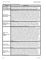
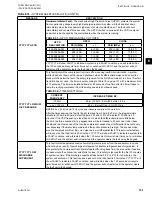
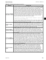
UNIT WARNINGS, UNIT SAFETIES (FAULTS) and
SYSTEM SAFETIES (FAULTS) sections.
Unit Warnings
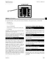
Unit warnings, as shown in
are caused when a condition is present requiring opera-
tor intervention to restart the unit. Check all setpoints,
program values, and options before operating the unit.
Warnings are not logged into the history buffer. If a
unit warning is in effect, the message will be displayed
when the operator presses the STATUS key.
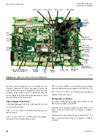
MICROBOARD (331-03478-XXX)
The 331-03478-xxx microboard was developed as
a direct replacement for the 031-02478-xxx line of
microboards. No adapter harness is required when re-
placing a 02478 with the new 03478. The 03478 uses
the IPUII processor card and provides some new fea-
tures for the chillers that the 02478 did not have. The
03478 program resides in flash memory instead of
EPROM. Program updates are accomplished by load-
ing the new program from an SD card inserted into the
SD card reader/writer. This same SD card reader/writer
also allows the user to datalog the operating param-
eters to an SD card every 5 seconds. This information
is invaluable when troubleshooting unit and system
problems since it allows the service technician to view
operating parameters before a unit fault. Details on the
new datalogging capability are explained in the OP-
TIONS Key area of this manual. A Real Time Clock/
BRAM keeps time and setpoints during power out-
tages.
Power Supplies and LEDs
The 03478 has LEDs to indicate various states of op-
eration of the microboard.
STATUS –
Flashes every ½ second to indicate that the
base board processor is running its program.
POWER –
On solid indicates that the base board +12V
and +5 V power supplies are operational.
TX1 –
Red LED flashes when transmitting data out
Port 1 TB3 (Future native communications BAS port)
RX1 –
Green LED flashes when receiving data in Port
1 TB3 (Future native communications BAS port)
TX2 –
Red LED that flashes when transmitting data
out Port 2 (E-Link TB2 or printer TB1)
RX2 –
Green LED that flashes when receiving data in
Port 2 (E-Link TB2 or printer TB1)
VSD_TX –
Red LED that flashes when transmitting
data out Port 3 to the VSD Logic board
VSD_RX –
Green LED that flashes when receiving
data in Port 3 from the VSD Logic board
Summary of Contents for QWC4
Page 14: ...QUANTECH 14 FORM QWC4 NM1 221 ISSUE DATE 02 28 2021 THIS PAGE IS INTENTIONALLY LEFT BLANK...
Page 64: ...QUANTECH 64 FORM QWC4 NM1 221 ISSUE DATE 02 28 2021 THIS PAGE IS INTENTIONALLY LEFT BLANK...
Page 82: ...QUANTECH 82 FORM QWC4 NM1 221 ISSUE DATE 02 28 2021 THIS PAGE IS INTENTIONALLY LEFT BLANK...
Page 130: ...QUANTECH 130 FORM QWC4 NM1 221 ISSUE DATE 02 28 2021 THIS PAGE IS INTENTIONALLY LEFT BLANK...
Page 146: ...QUANTECH 146 FORM QWC4 NM1 221 ISSUE DATE 02 28 2021 THIS PAGE IS INTENTIONALLY LEFT BLANK...
Page 152: ...QUANTECH 152 FORM QWC4 NM1 221 ISSUE DATE 02 28 2021 THIS PAGE IS INTENTIONALLY LEFT BLANK...
Page 155: ...QUANTECH 155 NOTES...


