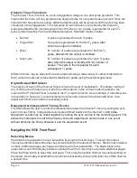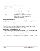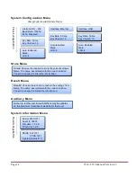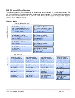
Page 8
9530/8530 Manual Version 4.5
3. Front Panel Overview
9530 Front Panel
Display Layout and Indicators
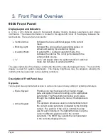
A 4 line x 20 character vacuum fluorescent display module displays parameters and status
information. The status information is located in the upper-left corner of the display, between the
two brackets. There are four enunciators:
Vertical Arrow
Indicates there are additional pages to the current
menu.
Blinking Light
Indicated the unit is actively generating pulses, or
armed and waiting for an external trigger.
Question Mark
In external PLL oscillator operation mode, this
indicates the internal PLL is not yet locked with the
external clock source.
“e”
An “e” will appear when the system clock is in external
mode, but not when in external with PLL.
The upper-right side of the display contains the title of the currently displayed menu. The rest of the
display is used for system parameters. The display brightness may be adjusted, allowing the
instrument to be used under various lighting conditions.
Description of Front-Panel Area
Keypads
Two keypad areas provide fast access to various menus and easy editing of system parameters.
Menu Keypad
Provides one touch access to the channel, trigger,
gate, and system menus for setting up the appropriate
parameters. The Page button will allow you to page
through the multiple levels of a menu, if multiple levels
exist.
Arrow Keypad
The up/down arrows are used to increment/decrement
the current cursor parameter (indicated by the blinking
cursor). The position of the cursor controls the step
size for each increment. The right/left arrows move the
cursor to different positions within the current
parameter. The NEXT key selects the next parameter
in the currently displayed menu.


