background image

Page 14

Quantum Composers 9520 Series Pulse Generator – Menu Structure

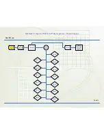
Recall Menu

#9 / 

Recall 

Button

Select/

Adjust

Recall #

Bin 1

Bin 2

Bin 10

Function 

Button

Bin 6

Bin 5

Bin 4

Bin 3

Bin 7

Bin 8

Bin 9

Bin 11

Bin 12

Bin 0

Next

Option to 

Enter Alpha-

Numeric 

Name

Summary of Contents for 9520 Series

Page 1: ...QUANTUM COMPOSERS INC PO Box 4248 Bozeman MT 59772 406 582 0227 phone 406 582 0237 fax www quantumcomposers com July 2007 Bootrom 1 02 FW 1 20 9520 Series Pulse Generator Operating Manual ...

Page 2: ......

Page 3: ......

Page 4: ......

Page 5: ...This document was created with Win2PDF available at http www daneprairie com The unregistered version of Win2PDF is for evaluation or non commercial use only ...

Page 6: ......

Page 7: ...e reached via one of the following methods Phone 406 582 0227 Fax 406 582 0237 Internet www quantumcomposers com Warranty In addition to a 30 day money back guarantee the 9520 has a one year limited warranty from the date of delivery This warranty covers defects in materials and workmanship Quantum Composers will repair or replace any defective unit Contact us for information on obtaining warranty...

Page 8: ...ze yourself with the equipment being tested and the location of its high voltage points However remember that high voltage may appear at unexpected points in defective equipment Do not expose high voltage needlessly Remove housing and covers only when necessary Turn off equipment while making test connections in high voltage circuits Discharge high voltage capacitors after shutting down power When...

Page 9: ......

Page 10: ......

Page 11: ... keypad areas provide fast access to various menus and easy editing of system parameters Channel Keypad Provides one touch access to the menus for setting up the channel parameters Pressing the appropriate let ter will display the parameters for the corresponding channel Arrow Keypad The up down arrows are used to increment decrement the current parameter indicated by the blinking cursor The posit...

Page 12: ...ing the knob will perform functions similar to the NEXT key and switch to the next pa rameter in the currently displayed menu Second Level Menus Function Key The second level menus indicated in yellow above certain keys are accessed through the use of the yellow FUNC key Pressing the FUNC key once and then pressing the desired menu key will display the specified second level menu Pressing the FUNC...

Page 13: ......

Page 14: ......

Page 15: ...Single Shot One To pulse is generated for each start command Burst n To pulses are generated for each start command Duty Cycle Once started To pulses cycle on and off continuously The To pulses are distributed to all of the start inputs of the Channel Timers and Mode Generators Output Pulses Output MUX Internal To Pulse External Input Arm Start Gate To Internal System Timer and System Mode Generat...

Page 16: ...ate input Output Multiplexer The output of the Channel Timers are routed to a set of multiplexers This allows routing of any or all Channel Timers to any or all of the unit outputs In the normal mode of operation the output of the nth Channel Timer is routed to the Tnth output connector As an example if a double pulse is required on Channel A output one can multiplex the Channel A timer with the C...

Page 17: ...on the speed The last entry mode is using the numeric keypad Enter the number including decimal point using the numeric keypad Complete the number using the EN TER key Errors may be corrected using the backspace key or to start over press the clear key CLR Pressing the CLR key a second time will exit the numeric keypad mode and restore the original number Entering Non Numeric Parameters When the c...

Page 18: ...nel Timers In the channel single shot mode and burst mode the Channel Timers may be rearmed after completing the initial output by pressing the FUNC key and RUN STOP key If there are channels currently running in normal mode single shot and burst channels can be re armed without affecting the timing on normal mode channels by pressing function RUN STOP Setting Pulse Timing Parameters Pulses are de...

Page 19: ...his allows double pulses and other com plex pulse trains to be generated Mux 00000101 The multiplexer is represented by a n bit binary number as shown above n is the number of channels Each bit represents a channel timer which is enabled by setting the bit to one In the above example timers A and C are combined on the current output Setting System Internal Rate Parameters The internal To period co...

Page 20: ......

Page 21: ... o n fig u ra tio n C ha nne l E na b le C ha nne l E na b le C ha nne l E na b le P o la rity P o la rity P ulse w id th O utp ut Typ e TTL O p tica l O utp ut Typ e A d justa b le D e la y O utp ut L e ve l C h a n n e l M o d e C h a n n e l M o d e C h a n n e l M o d e C h a n n e l M o d e W a i t M e n u M u l t i p l e x e r M e n u C h a n n e l E n a b l e C h a n n e l E n a b l e C h a...

Page 22: ...rameters Comm Parameters Comm Parameters Keypad Parameters Misc Parameters Interface RS232 Interface USB Interface GPIB Key Repeat Rate Auto Start Baud Rate Baud Rate Address Key Volume Decimal Mark Echo Enable Knob Volume LCD Brightness Gate Mode Gate Mode Gate Disabled Gate Enabled Threshold Polarity GATE Menu Trig Mode Trig Mode Trig Disabled Trig trig mode Threshold Edge TRIG Menu ...

Page 23: ...essing the RUN STOP key after the unit has been disarmed will generate a new pulse train Channel Menus To Mode To Mode To Mode To Mode MOD E C ontinuous MOD E Single Shot MOD E Burst MOD E D uty C ycle On C ycle Burst Off C ycle T i m i n g P a r a m e t e r s P u l s e C o n f i g u r a t i o n P u l s e C o n f i g u r a t i o n C h a n n e l E n a b l e C h a n n e l E n a b l e C h a n n e l E...

Page 24: ... mode Setting Pulse Mode of Operation Each channel may be set independently to operate in one of four modes normal single shot burst or duty cycle within the CHANNEL menus Mode Selects the mode for the current channel Additional parameters are provided for the burst mode and the duty cycle mode Brst Sets the number of pulses in the burst mode to gener ate before inhibiting output On Sets the numbe...

Page 25: ...nables the GATE input for the channel by setting the method of output control used with the gating function Logic Sets the logic level used with the gating function either active high or active low Pulse Inhibit method the gate prevents the channel from being triggered by the channel s trigger source pulse If a pulse has already started when the gate disables the channel the pulse will continue no...

Page 26: ...enabling the trigger mode s Level Sets the trigger threshold Edge Selects between rising edge falling edge as the trig ger source when a trigger mode is enabled Setting the Clock Source and Internal Rate Source Selects the internal or external clock source from which the unit will operate Per Sets the To period which determines the fundamental output frequency of the unit Setting the Output Refere...

Page 27: ...s incremented In addition the volume of the beep can be controlled for both the keypad and the adjustable knob Key Rate Sets the rate at which the keys will repeat when held down Key Vol Sets the beep volume for the keypad Knob Vol Sets the beep volume for the Rotary Knob Setting the Auto Start Mode The unit may be configured to automatically start generating pulses after power up Setting the Disp...

Page 28: ...C store NOTE When the unit powers up it will recall the last stored or recalled configuration Any changes to the configuration which were not saved are not restored Recall Menu Recalling System Configurations Use the following procedure to recall a stored or default system configuration Enter the Recall Menu FUNC recall Select a configuration number From the Recall Menu press the recall key sequen...

Page 29: ......

Page 30: ......

Page 31: ...ATE key Set the desired pulse period Note that in general the pulse delay plus the pulse width plus a 75ns hardware reset constant for any channel must be less than the To period Start Press the RUN STOP key to start generating pulses Stop Press the RUN STOP key a second time to stop gen erating pulses Quick Start Normal External Trigger Operation To generate a single pulse for every external trig...

Page 32: ...sed to trigger all the channel timers Sys tem modes are controlled via the MODE menu To Use Continuous Mode The RUN STOP button starts and stops a continuous pulse stream at the rate specified by the Rate menu This corresponds to the normal output mode for most pulse generators To generate a continuous stream of pulses within the system Modemenu Mode Select Continuous for the system mode within th...

Page 33: ... Duty Cycle mode On Set the number of pulses to produce during the on cycle Off Set the number of pulses to skip during the off cycle within the Rate menu Source Select the system oscilator or the external clock in fre quency Period Set desired Period Channel Timer Overview The output of each channel is controlled by two timers to generate the delay timing and the pulsewidth All channels are simul...

Page 34: ...me the RUN STOP key is pressed If the unit is in the active state i e channels which are set to the Normal mode are producing pulses pressing the FUNC RUN STOP key sequence will reset the Burst counters and generate a new set of pulses in sync with the other channels running in the Normal mode FUNC RUN STOP will not affect To pulse status To use the Burst mode within the Channel menus Enable Selec...

Page 35: ...the pulse will continue normal output but will not restart on the next pulse In Ouput method the gate leaves the base triggering alone and enables disables the output directly External Input Overview The external inputs may be used to trigger the unit or to gate the system or channel timers When using a trigger input the external input acts as a system start pulse Depending on the system mode the ...

Page 36: ...nit is reset at the end of a burst and will generate another set of pulses upon receiving a new trigger Triggers that occur in the middle of a burst are ignored Pressing the RUN STOP key will disarm the unit To Start a Continuous Stream of Pulses Using the External Trigger The external trigger may be used to start the unit generating pulses within the Mode menu Mode Select the Continuous mode with...

Page 37: ... to cycle through Advanced Chan nel Menu within the Mode menu Mode Select the desired mode within the Rate menu Source Select the system oscilator or an external clock in fre quency Per Set the period between pulses within the Gate menu Mode Select pulse INH or output INH Level Set the gate threshold level Logic Select active high or active low Pressing the RUN STOP key will arm the unit Once the ...

Page 38: ......

Page 39: ...k of the unit 1 No Connection 2 Tx Transmit to computer 3 Rx Receive from computer 4 DTR Connected to pin 6 5 Ground 6 DSR connected to pin 4 7 RTS connected to pin 8 8 CTS connected to pin 7 9 No Connection The serial port parameters should be set as follows Baud Rate 4800 9600 19200 38400 57600 115200 default Data Bits 8 Parity None Stop Bits 1 The default baud rate for the RS232 is 115200 USB I...

Page 40: ...accomplished via USB The BAUD rates on the pc and on the pulse generator must match for successful communication The USB port s BAUD rate on the pulse generator can be set using the SCPI command SYSTem COMMunicate SERial USB n where n can be o 4800 o 9600 o 19200 o 38400 default o 57600 o 115200 USB 1 0 specification is used The USB cable can be removed without unplugging the device in the operati...

Page 41: ... the Digi Connectware s Realport Drivers setup must be used to install the COM port on the pc This virtual COM port is then local to the computer it was installed on Please refer to the Digi Connectware documentation supplied on the cd or call Quantum Composers technical support The pulse generator s SCPI parameter SYSTem COMMunicate SERial USB n is defaulted to 115200 and should not be changed fo...

Page 42: ...erminators For this reason it is not recommended that multiple commands be stacked together into single strings as is common with some other types of instruments It is recommended that the coded application send a single command in a string and follow immediately by reading the response from the unit Repeat this sequence for multiple commands IEEE 488 2 Common Command Format The IEEE 488 2 Common ...

Page 43: ...er If more than one parameter is used you must separate subsequent parameters with a comma SCPI Optional Keywords Optional keywords and or parameters appear in square brackets in the command syntax Note that the brackets are not part of the command and should not be sent to the pulse generator When sending a second level key word without the optional keyword the pulse generator assumes that you in...

Page 44: ...ct prefix i e no colon or to start command 2 Missing command keyword 3 Invalid command keyword 4 Missing parameter 5 Invalid parameter 6 Query only command needs a question mark 7 Invalid query command does not have a query form 8 Command unavailable in current system state Programming Examples Example 1 20 ms pulsewidth 2 3 ms delay 10 Hz internal trigger continuous operation PULSE1 STATE ON cr l...

Page 45: ... to the selected channel STATe boolean value Std Enables Disables the selected channel output If To is selected all output is affected Enabling To is the same as pressing the RUN button Example 2 25 s pulsewidth 0 delay external trigger one pulse for every trigger PULSE1 STATE ON cr lf enables channel A PULSE1 POL NORM cr lf sets polarity to active high PULSE WIDT 0 000025 cr lf sets pulsewidth to...

Page 46: ... EXT20 EXT25 EXT40 EXT50 EXT80 EXT100 New Sets Source for the external rate generator System Clock or External Source ranging from 10MHz to 100MHz OCLock To 10 11 12 14 16 20 25 33 50 100 New Sets external clock output To Pulse or 50 duty cycle TTL output from 10MHz to 100MHz GATe New Subsystem Contains the commands to define the Gate function MODe DIS PULS OUTP CHAN New Sets Global Gate Mode Disa...

Page 47: ... g a tive tha n the firs t O U T P ut N e w S ub s ys te m C o nta ins c o m m a nd to c o ntro l o utp ut m o d e A M P L itud e num e ric va lue s N e w S e ts a d jus ta b le o utp ut le ve l M O D e T T L A D J us ta b le N e w S e le c ts o utp ut A M P L itud e m o d e T T L C M O S A D J us ta b le C M O D e N O R M a l S IN G le B U R S t D C YC le N e w C ha nne l M o d e S e ts the c ha ...

Page 48: ...e m C o ntro ls the p hysica l co nfigura tion o f the RS 2 32 p o rt B A UD 4 8 0 0 96 0 0 1 9 2 00 38 4 0 0 57 6 0 0 11 5 2 0 0 Std S e ts the b a ud ra te fo r b o th rece iving a nd tra nsm itting using the D B 9 RS 2 32 p o rt US B 4 8 0 0 96 0 0 1 9 2 00 38 4 0 0 57 6 0 0 11 5 2 0 0 Ne w S e ts the b a ud ra te fo r co m m unica tion when using m a p p e d com p o rts fo r US B and E therne ...

Page 49: ...rigger Generates a software trigger pulse Operation is the same as receiving an external trigger pulse LBL Setup Label string value Query Form returns the label of the last saved or recalled configuration Command Form sets the label string for the next sav command String must be in double quotes 14 characters max Keyword Parameter Std New Comments DISPlay Std Subsystem Contains commands to control...

Page 50: ......

Page 51: ... 000MHz RESOLUTION 5ns ACCURACY Same as timebase JITTER 200ps SETTLING 1 cycle BURST MODE 1 to 10 000 000 TTL ADJUSTABLE OUTPUTS NUMBER 2 4 or 8 Channel Outputs LOAD 50 ohm RISE TIME 3ns typ TTL 15ns typ 20V high imp Adj 25ns typ 10V 50 ohms Adj SLEW RATE 0 5 V ns TTL 0 1V ns Adj OVERSHOOT 100mV 10 of pulse amplitude LEVELS TTL 0 to 4 VDC VAR adjustable amplitude 2 0 to 12 0 VDC with 10mV res 12 0...

Page 52: ...LARITY Active High Active Low FUNCTION Pulse Inhibit or Output Inhibit CHANNEL BEHAVIOR Global w Individual Channel PULSE INHIBIT DELAY 120ns OUTPUT INHIBIT DELAY 45ns OPTICAL OUTPUTS NUMBER 2 4 or 8 WAVELENGTH 820nm or 1300nm MAXIMUM SIGNAL RATE 5MBd MAXIMUM LINK DIST 1 5km CONNECTOR TYPE ST RESOLUTION 500ps ACCURACY 1ns 001 x Delay OPTICAL INPUTS NUMBER 0 2 or 4 WAVELENGTH 820nm or 1300nm MAXIMU...

Page 53: ...RNAL CLOCK IN 10MHz 100MHz User selectable in descrete values V in 3V min EXTERNAL CLOCK OUT 10MHz 100MHz User selectable in descrete values COMMAND SET COMPATIBILITY Backwards Compatible OPTIONS I Incrementing COM Extended Communications Ethernet GPIB MODULES Standard Dual TTL Adjustable Dual High Voltage Dual Optical Dual Standard Input Module Dual Optical Input Module ...

Page 54: ... fluctuations are not to exceed 10 of the nominal supply voltage Pollution Degree 2 Installation overvoltage Category II for transient overvoltages Maximum Relative Humidity 80 RH non condensing Operating temperature range of 0o C to 40o C Storage and transportation temperature of 40o C to 70o Maximum altitude 3000 m 9843 ft This equipment is suitable for continuous operation This section provides...

Page 55: ......

Page 56: ......

Page 57: ......

Page 58: ...ely 4 s with some droop To maintain the highest possible rise time care must be taken with cabling and termination Low capacitance cable and 50 ohm termi nation will provide the fastest rise times without overshoot Faster rise times can be achieved by increasing the termiantion resistance but some overshoot is likely to occur 35V Specifications Output 5V 35V Setpoint Resolution 10mV Rise Time 30ns...

Page 59: ...signates the Trig input and the G designates the Gate input The Level for the Gate input can also be adjusted from the Gate menu Once you have enabled the triggering functionality of the unit you can then choose which channels will be triggered off of the Gate input and which chan nels will be triggered off of the Trig input This selection can be done in the secondary channel menus which are acces...

Page 60: ...S e e IN S Trum e nts s ub s ys te m C T R ig g e r Trig G a te N e w A llo w s the s e le c tio n o f w hic h inp ut trig g e r to us e T R IG g e r N e w S ub s ys te m C o nta ins c o m m a nd s to c o ntro l the inp ut trig g e r p a ra m e te rs G E D G e R IS ing o r F A L L ing N e w S e le c ts w hic h e d g e the G a te inp ut trig g e rs o n P U L S e 0 N e w S ub s ys te m C o nta ins c...

Page 61: ...user to have a 50 Ohm load on the output while maintaining an output amplitude of at least 4 Volts while in the TTL CMOS mode All other functionality of the module is the same as the AT20 modules including output while using the AdjustableMode Function of the channels ...

Page 62: ... Notes The Digi Connectware s Digi Device Discovery can be used to determine what IP address was assigned by the local DHCP server if any Digi Device Discovery can also be used to open a web interface to the Ethernet module Simply double click on the IP address that is displayed in the Digi Device Discovery utility Username root Password dbps If a mapped COM port is the desired communication metho...

Page 63: ...programming commands IEEE 488 2 Common Commands and Standard Commands for Programmable Instruments SCPI The format is the same for all interfaces Hyperterminal in Windows or any other generic terminal program may be used to interactively test the commands using the RS232 interface ...

Page 64: ...een reset to factory defaults before it left the manufactur ing facility In this mode it is ready to be assigned an IP address by the local DHCP server If a crossover cable is being used the Ethernet device will as sume a default IP address The Digi utility Digi Device Discovery can be used to determine the IP address that is currently assigned to the Ethernet module Hit Start All Programs Digi Co...

Page 65: ... can be made from the web inter face Please note however that if the IP address is changed such that it is incompatible with the LAN all communication including access to the module s settings including the IP address will no longer be possible over the LAN If this happens a crossover cable must be used to access the Digi module s settings again using Digi Device Discovery Temporarily set the pc s...

Page 66: ...This document was created with Win2PDF available at http www daneprairie com The unregistered version of Win2PDF is for evaluation or non commercial use only ...

Page 67: ...se Generator Menu Structure Channel Menus The following can be used to access Channels A through H Channel Button Select Adjust Channel Enable Disable Enable Disable Next Width Select Adjust Width Adjust Next Delay Select Adjust Delay Adjust ...

Page 68: ...Channel Menus The following can be used to access Channels A through H Channel Button Select Adjust Channel Enable Disable Enable Disable Next Polarity Select Adjust Active High Active Low Next Output Select Adjust TTL CMOS Adjustable Select Adjust Amplitude Adjust Next ...

Page 69: ...ucture Channel Menus The following can be used to access Channels A through H Channel Button Select Adjust Channel Enable Disable Enable Disable Next Mode Select Adjust Normal Single Shot Select Adjust Duty Cycle Burst Select Adjust Burst Count Off Count On Count ...

Page 70: ...osers 9520 Series Pulse Generator Menu Structure Channel Menus The following can be used to access Channels A through H Channel Button Select Adjust Channel Enable Disable Enable Disable Next Wait Select Adjust Wait Count ...

Page 71: ...u Structure Channel Menus The following can be used to access Channels A through H Channel Button Select Adjust Channel Enable Disable Enable Disable Next Mux Select Adjust Select which internal channel timers you want combined on the current physical output ...

Page 72: ...anced function for Channels A through H Channel Button Select Adjust Channel Enable Disable Enable Disable Next Ch Gate can only be used if system gate is in Chan Menu mode Select Adjust Disabled Function Button Output Inhibit Pulse Inhibit Active High Active Low Active Low Active High Select Adjust Select Adjust Logic Logic Next Next ...

Page 73: ...re Advanced Channel Menus The following can be used to access the advanced function for Channels A through H Channel Button Select Adjust Channel Enable Disable Enable Disable Next Select Adjust To Trig Function Button Ch A Ch D Ch C Ch E Ch B Ch F Synch Source Ch G ...

Page 74: ...r Menu Structure Gate Menu Gate Button Select Adjust Mode Disabled Pulse Inhibit Next Level Adjust Next Logic Select Adjust Active High Active Low Pulse Inhibit Next Level Adjust Select Adjust Active Low Next Logic Active Low Chan Menu Next Level Adjust ...

Page 75: ...ulse Generator Menu Structure Trigger Menu Trigger Button Select Adjust Mode Disabled Triggered Next Level Adjust Next Edge Select Adjust Falling Edge Rising Edge Lo Jitter Next Level Adjust Select Adjust Rising Edge Next Edge Falling Edge ...

Page 76: ...m Composers 9520 Series Pulse Generator Menu Structure System Mode Menu 1 Mode Button Function Button Select Adjust Normal Single Shot Select Adjust Duty Cycle Burst Select Adjust Burst Count Off Count On Count Mode ...

Page 77: ...System Menu Select Adjust Interface RS232 3 System Button Function Button Select Adjust Baud Rate 4800 Next 9600 115200 57600 38400 19200 Echo Next USB Select Adjust Baud Rate 4800 Next 9600 115200 57600 38400 19200 Echo Next GPIB Ethernet Select Adjust Address Next 1 15 ...

Page 78: ...Series Pulse Generator Menu Structure Rate Menu 4 Rate Button Select Adjust Clock Source System Osc 10 MHz Ext Next Period Select Adjust Period Adjust Function Button 50 MHz Ext 40 MHz Ext 25 MHz Ext 20 MHz Ext 80 MHz Ext 100 MHz Ext ...

Page 79: ...ers 9520 Series Pulse Generator Menu Structure Store Menu 6 Store Button Select Adjust Store Bin 1 Bin 2 Bin 10 Function Button Bin 6 Bin 5 Bin 4 Bin 3 Bin 7 Bin 8 Bin 9 Bin 11 Bin 12 Next Option to Enter Alpha Numeric Name ...

Page 80: ...9520 Series Pulse Generator Menu Structure Recall Menu 9 Recall Button Select Adjust Recall Bin 1 Bin 2 Bin 10 Function Button Bin 6 Bin 5 Bin 4 Bin 3 Bin 7 Bin 8 Bin 9 Bin 11 Bin 12 Bin 0 Next Option to Enter Alpha Numeric Name ...

Page 81: ...Page 15 Quantum Composers 9520 Series Pulse Generator Menu Structure Info Page 0 Info Button Function Button Contains Product Information ...

Reviews: