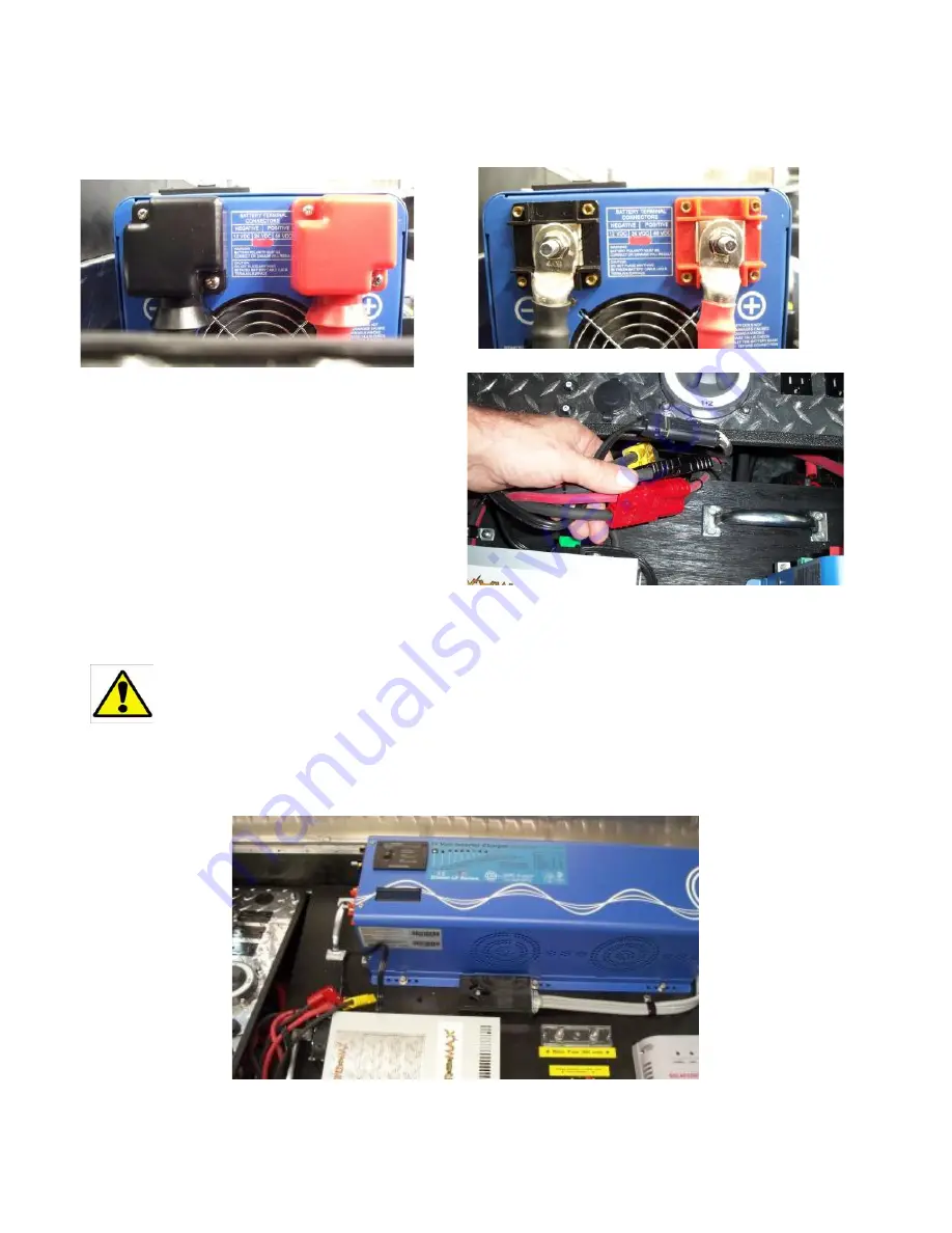
Step 3:
Below;
Remove the screws securing the plastic cable guards on the end of the inverter closest
to the control panel, and remove the guards. Using a 1/2” wrench or socket, remove the nuts and cables
from the DC side of the inverter.
Step 4:
Right;
, Disconnect the 4 connectors
detailed below, and place all the cables up and
out of the way. Tuck the inverter and fuse
block cables down under the control panel to
avoid having them catch on the power board
during removal.
Step 5:
Below;
(The power board assembly weighs over 120 lbs, so to avoid injury, or unit
damage, it is highly recommended that this step be accomplished by 2
people.)
Using the handles provided, tilt the inverter side up and rotate the entire assembly up and out of
the case, being careful to avoid damaging the RF gasket around the case opening.
17
Summary of Contents for 5000-60 TSW
Page 2: ......
Page 9: ...7 ...
Page 25: ...Cable A Cable B Cable C Cable E Cable D Cable F 23 ...
Page 26: ...Cable G Cable H Cable I 24 ...


