background image

17 


APPENDIX 2. SERIAL COMMUNICATIONS FOR THE TC 1 
TEMPERATURE CONTROLLER 

7/26/2013 


This document provides the serial communications protocols for version 1.0 of the firmware on the 

TC 1

 family of controllers: 


TC 1

/t2 – for the t2, single temperature controller 


TC 1

/t2x2 – for the t2x2, dual temperature controller for sample and reference 


TC 1

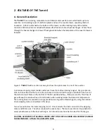
/Turret 6 – for the Turret 6, 6‐position turret 

The version number and the ID (see below) are shown briefly on the display when the temperature 
controller is turned on. 

 
All functions of the temperature controller can be managed from a computer, using the command 
set described below.  If you purchased your unit as a component of a spectrometer from certain 
manufacturers, this feature may be implemented through traditional RS232 serial connectors on the 
computer or the spectrometer and on the controller.  In this case they will be connected by a 
standard 15‐pin serial extension cable (male connector on one end and female on the other).  No 
driver installation should be needed. 
 
Otherwise the serial linkage will be established through a USB connection between the computer and 
the controller.  In this case the controller includes electronics which convert the USB connection to a 
serial communications port.  However, for the port to be available to programs on the computer it 
will be necessary to load driver software.  It is important that the driver software be loaded before 
connecting a USB cable between the controller and the computer.  Contact Quantum Northwest for 
further information. 
 
Quantum Northwest can provide a control program written specifically for control of all functions of 
the temperature controller.  Ask for program T‐App. 
 
In programming for the 

TC 1

 controller, one must adhere to the conventional notation: 8/N/1. 


Baud: 


19200 


Data Bits:   


Parity: 


None 


Stop Bit: 


Flow Control: 

None 

For many of the commands listed below the controller returns information in response to the 
command.  All commands and responses are delineated by left and right square brackets ( [  ] ).  Any 
text sent to the controller not enclosed within brackets will be ignored.  In this document an ellipsis 
(……) is used to distinguish responses from commands. 


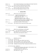
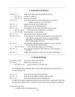
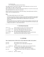
[command] 

Purpose of the command (sent to the controller). 

......[response] 

Meaning of the response (received from the controller). 


Summary of Contents for Turret 6/AP

Page 1: ...el 509 624 9290 Fax 509 624 9488 E mail quantum qnw com Web www qnw com Turret 6 AP 6 Position Temperature Controlled Cuvette Turret for the Applied Photophysics Chirascan Manual Product Overview Janu...

Page 2: ...Turret 6 8 A General Description 8 B Cuvettes 9 C Cuvette z Height 9 D Cooling Water for the Peltier 9 E Dry Gas Purging 10 F External Temperature Probe 10 G External Computer Control 10 H Manual Rese...

Page 3: ...mputer control of the TC 1 Temperature Controller With this software the temperature of the sample holder and a temperature sensed by an external probe may be plotted vs time Simple text scripts may b...

Page 4: ...t start automatically locate the SETUP exe file in the root directory and run it The installation process starts with a small black window that is shown during installation of the drivers needed to co...

Page 5: ...Press SET to initiate temperature control The temperature will rise and stabilize indicated by the change in the green LED light on the front panel from flashing to steady To control stirring go to t...

Page 6: ...ess SET to retain this new Target and initiate temperature control The green LED light will begin flashing slowly as the device seeks the targeted temperature and the page window will show the Current...

Page 7: ...is 0 01 C minute If needed much slower ramps may be set through software commands Discontinue Ramping Press SET while the Ramp is on shown by nonzero Current min to turn the Ramp off The page will upd...

Page 8: ...ve rotating magnet Dry gas enters a 1 16 inch hose barb on the front of the instrument and is carried through a manifold in the floor of the turret to small holes on the bottom of the 18 cuvette windo...

Page 9: ...polarity is reversed and it transfers heat from the heat exchanger to the tower When cooling it is particularly important to transfer this heat away from the Peltier This is accomplished with flowing...

Page 10: ...1 Temperature Controller This jack will accept the plug on a standard Series 400 or Series 500 thermistor probe When a probe is plugged into the jack the probe temperature is presented on the display...

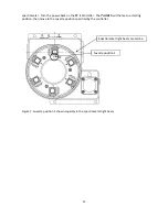
Page 11: ...Controller The Turret 6 will home to a starting position then move to the cuvette position specified by the controller Figure 7 Cuvette position 1 shown squarely in the spectrometer light beam Cuvett...

Page 12: ...out of range warnings loose cable check cable The temperature controller is not receiving reasonable responses from either the cell tower or heat exchanger sensors Since it is very unlikely for both...

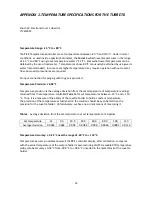
Page 13: ...ature range 20 to 110 C temperature precision 0 02 C cuvette size outside dimensions 12 5 x 12 5 mm minimum cuvette height 30 mm cuvette z height 15 mm optical port dimensions 12 mm high x 10 mm wide...

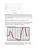
Page 14: ...om the set temperature of temperature readings returned from the temperature controlled Turret 6 for set temperatures between 15 C and 110 C Thus it is a measure of the ability of the cuvette holder t...

Page 15: ...roducibility is a measure of the ability of the temperature to return to an original value see Figure 1 It accounts for differences depending on the direction of temperature change and differences fro...

Page 16: ...re shown the time required to get within 1 C the time to get within the lock on temperature of 0 05 C from the target and the final time by which the TC 1 indicates the temperature is stable Temperatu...

Page 17: ...e will be established through a USB connection between the computer and the controller In this case the controller includes electronics which convert the USB connection to a serial communications port...

Page 18: ...r speed is 2500 rpm F1 LS What is the lowest stirrer speed F1 MS 300 The lowest stirrer speed is 300 rpm F1 SS S 1000 Set stirrer speed to 1000 rpm F1 SS S 0 Turn stirrer off and set the speed to zero...

Page 19: ...top automatic reports of instrument status F1 IS R The controller has been powered off and back on again 7 Current Sample Temperature F1 CT What is the current temperature of the holder F1 CT 22 84 Th...

Page 20: ...n F1 PA Start automatic reporting of probe temperature every temperature increment set by the command above F1 PT 30 5 The current probe temperature is 30 5 degrees F1 PA Stop automatic reporting of p...

Page 21: ...l send a response of the form F1 TT as a notification of the end of the ramp This response can be blocked at any time by previously sending the command F1 TT see command class 5 11 Heat Exchanger Temp...

Page 22: ...buttons and the display on the front When a computer program is in use the TC 1 will automatically send reports to the program whenever a manual change has been made The commands in this section are i...

Page 23: ...23 R1 TT R Stop reporting manual changes for the reference target temperature R1 RR R Stop reporting manual changes for the reference ramp rate...

Reviews: