background image

Owners Manual 

Quantum Energy Technologies


Section 5: OPERATION 

5a: Pre Start Up 

1.


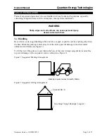
The hot-water system should be flushed and cleaned. Proper water treatment is required to 
prevent corrosion and scale formation on the condenser. 

2.


Inspect all water piping for flow direction and correct connections at the condenser. 

3.


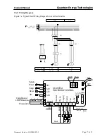
Open all electric disconnects and check all electric connections for tightness. Check unit power 
supply wiring for proper amperage and a minimum insulation temperature of 75°C. Check for 
proper phasing using a phase sequence meter. 

4.


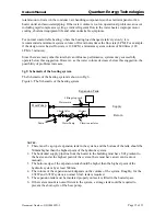
Verify water temperature sensor is installed in the exiting water line (supply to a water tank or 
building) for water heaters and building heaters, and the entering water line for pool heaters. On 
all Quantum units the sensors are factory mounted. 

5.


Check that the voltage of the power supply to the unit is within ±10% of the nameplate rating. 
Verify all mechanical and electrical inspections have been completed according to local codes. 

6.


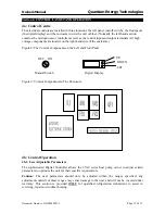
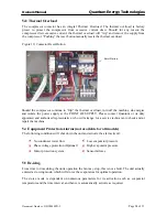
Turn on the controller via the on/off switch mounted on the left panel of the cabinet. The 
Digital Controller will display the current water outlet temperature (for building heaters and 
water heaters) and the inlet temperature (for pool heaters). This will energize the system. (If 
crankcase heater is equipped, wait at least 

24 hours

 before starting up the unit.) 

7.


Open all water flow valves and start the hot water pump. Check all piping for leaks and vent the 
air from the condenser as well as from the system plumbing for a building heater.  


5b: Commissioning 

1.


If the controller calls for heating, the unit will begin the start-up sequence. Please be aware that 
there is a 10-minute time delay, after activation, prior to a compressor start. 

2.


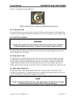
After running the unit for a short time, check the rotation of fans, and flashing in refrigerant 
sight glass.  The refrigerant sight glass should be clear with a solid column of liquid visible.  

3.


Allow the compressor to run a short time, but at the same time be ready to stop it immediately if 
any unusual noise or adverse conditions appear. 

4.


With an ammeter, verify that each phase of the compressor and the fan(s) are within the RLA as 
listed under Electrical Data. 

Adjust the damper for the centrifugal fan system to ensure that the 

electrical current for each fan is less than 4 amps

.  

5.


Check the system operating parameters such as the head pressure and the water temperature as 
well as the suction pressure and the ambient temperature. The pressures can be measured with 
manifold gauges. 

6.


Verify superheat temperature is in the range of 4°C – 7°C at about 10°C ambient. The superheat 
may be large, at low ambient temperatures for a TX valve, and at high ambient temperature for 
an Electronic Expansion Valve. The superheat for an Electronic Expansion Valve is determined 
from the suction temperature and the suction pressure measured by the gauge, not directly read 
from the controller.  


Document Number : QDC0049PD-5 


Page 22 of 33


Summary of Contents for 67ACW2-134

Page 1: ...MANUAL Including Installation Instructions and Warranty Information To Suit 67AC HEAT PUMP WATER POOL FLOOR HEATERS MODELS 67ACW2 134 67ACW2 134 C 67ACW 134 67ACW 134 C 67ACW 417 67ACW 417B 67ACP2 22...

Page 2: ...TION 9 3a Handling 9 3b Location 10 3b 1 Unit Placement 10 3b 2 Service Access 10 3b 3 Clearances 11 3b 4 Sound Isolation 11 3b 5 Vibration Isolation 11 3b 6 Damper for Centrifugal Fan Models 11 3c Re...

Page 3: ...ttons 20 4b 3 SET Button 20 4b 4 UP Button 20 4b 5 Down Button 20 4b 6 Programming Menu 20 4b 7 Adjusting 20 4b 8 Operating Principle 21 4b 9 Fault Codes 21 Section 5 OPERATION 22 5a Pre Start Up 22 5...

Page 4: ...vered By Warranty 31 7c Before Phoning For Service 31 List of Figures Figure 1 Suggested Pushing Arrangement 9 Figure 2 Suggested Lifting Arrangement 9 Figure 3 Clearance Requirements 10 Figure 4 Typi...

Page 5: ...tate Territory Postcode Date of Purchase Purchased From Model Serial Number Date of Manufacture Details on Data Plate on water heater 1b Installer s Details Date of Installation Installer s Name Addre...

Page 6: ...ture reservoir It has a cold side to absorb heat at low temperatures and a hot side to deliver heat at high temperatures The Quantum system has an air coil as the cold side of the refrigeration circui...

Page 7: ...sical damage after the unit leaves the factory For unit shipping weights see section 2d 1 Physical Data Table 2d Physical Data 2d 1 Physical Data Table PHYSICAL DATA 67ACW2 134 67ACW2 134 C 67ACW 134...

Page 8: ...OFF POWER BEFORE OPENING COVER 1225 360 210 1121 1425 1175 920 1121 Model No67A CW2 134 C Serial No SUZ0027 Date of MfgDec 2006 Hot Water Generating Rate542 l h Heating Capacity22 10 kW Power Input t...

Page 9: ...the unit Do not push or pull the unit by anything other than the base Block the pushing vehicle away from the unit to prevent damage to the sheet metal cabinet and end frame see Figure 1 To lift the...

Page 10: ...cated wind deflectors 3b 2 Service Access Each end of the unit must be accessible after installation for periodic service Compressor filter drier and liquid line solenoid valve are accessible from the...

Page 11: ...necessary locate the unit away from sound sensitive areas Avoid locations beneath windows or between structures where normal operating sounds may be objectionable Reduce structurally transmitted sound...

Page 12: ...and pressure indicators located close to the unit to aid in unit servicing 7 A strainer or other means of removing foreign matter from the water before it enters the pump Place the strainer far enoug...

Page 13: ...ated As a guide the following parameters should be used Calcium Hardness 70 150 mg L 3e 3 Pool Heater Applications It is imperative that the correct chemical balance be maintained in your pool and or...

Page 14: ...owever if desired an external by pass can be plumbed in for use if the heater is disconnected or to isolate it from the hydraulic circuit In this way water would still flow but not through the heater...

Page 15: ...the heating system The Schematic of the heating system is shown in Fig 6 Figure 6 The Schematic of the heating system Expansion Tank NOTES 1 There must be a proper expansion tank in the system and the...

Page 16: ...11 111 Locked Rotor Amps LRA Fan 6 5 24 6 5 NOTES 1 Voltage within 10 of nameplate rating 2 Phase imbalance within 3 3 Single conductors should be used for power connections 4 Single point disconnect...

Page 17: ...R N 16 L1 L1 L3 L2 QF1 FR1 0 48 L N QUANTUM ELECTRONICCONTROL Air De ice Comp Water LP HP Neutral YV YV KM1 N ST1 EH DIV LIV COMP FAN 1 2 3 4 5 7 11 12 13 ST2 ST3 ST4 14 Comp Fanand LP HPProtection 1...

Page 18: ...R2 L N QUANTUM ELECTRONIC CONTROL Air De ice Comp Water L P H P Neutral Y V K M 1 N S T 1 E H D I V L I V C O M P F A N 1 2 3 4 5 7 1 2 1 3 S T 2 S T 3 ST4 1 4 Comp Fan and LP HP Protection 1 0 W P K...

Page 19: ...nents on the Left and Front Panel UP Figure 9 Control Components In The Enclosure 4b Control Operation 4b 1 User Adjustable Parameters The sophisticated Digital Controller allows the 67AC series heat...

Page 20: ...ture c During the time delay start period press hold for 3 seconds to force a compressor start When the compressor is running press hold for 3 seconds to force a compressor shutdown 4b 5 DOWN Button a...

Page 21: ...ower than the ambient temperature and this temperature difference lasts for 5min de icing is activated During the de icing time the fan stops When the evaporator temperature rises to 8 C 2nd Level F08...

Page 22: ...nd start the hot water pump Check all piping for leaks and vent the air from the condenser as well as from the system plumbing for a building heater 5b Commissioning 1 If the controller calls for heat...

Page 23: ...the flow switch will close once satisfactory flow rate is achieved If the hot water temperature is below the stage on temperature and all equipment protection devices are closed the unit will start Th...

Page 24: ...or its duly appointed and authorised representative who will arrange for a service technician to check and or repair the machine 5e Equipment Protection Alarms not available for all models The followi...

Page 25: ...ble to advise if the noise being produced is abnormal 6b 3 Frost on Sump No frost should be present on the sump of the compressor 6c Refrigerant Sight Glass Observe the refrigerant sight glass weekly...

Page 26: ...ally required except the occasional removal of dirt and debris from the outside surface of the fins Clean as often as necessary to keep the coil free from foreign matter For cleaning use locally purch...

Page 27: ...problem can be traced to the power element only unscrew the element from the valve body without removing the valve but only after pumping the unit down WARNING Disconnect and tag out all power source...

Page 28: ...ould be wired to open whenever the liquid line solenoid valve is energized This can be accomplished by wiring the hot gas solenoid in parallel with the liquid line solenoid The pressure control is fac...

Page 29: ...ould not de ice completely 7 Crankcase heater burned out 1 Check and fix the flood back problem Add oil if necessary 2 Find and repair the leakage Add oil if necessary 3 Purging the system and change...

Page 30: ...such defect NOTE Corrosion of the heat exchanger is caused by improper water quality PH balance Corrosion of this nature will void all warranties THE WARRANTY SHALL NOT APPLY IN ANY OF THE FOLLOWING...

Page 31: ...irements Relocation of equipment due to complaints of noise level or inappropriate location No responsibility shall be accepted for damage to the system or property if it is found that continued use o...

Page 32: ...Owners Manual Quantum Energy Technologies Customer Notes Document Number QDC0049PD 5 Page 32 of 33...

Page 33: ...ALIA A B N 88 095 959 327 Phone 61 2 9699 7444 Fax 61 2 9699 5386 NOTE While every care has been taken to ensure the accuracy in preparing this publication No liability can be accepted for any consequ...

Reviews: