


Owners Manual
Quantum Energy Technologies
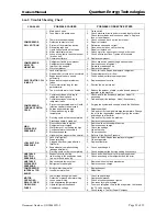
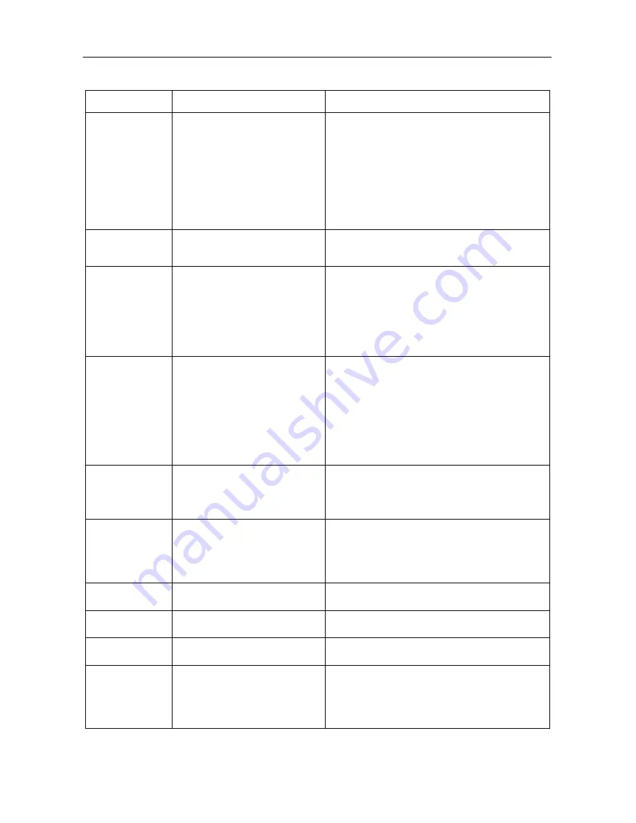
6m.1: Trouble Shooting Chart
PROBLEM
POSSIBLE CAUSES
POSSIBLE CORRECTIVE STEPS
COMPRESSOR
WILL NOT RUN
1. Main switch open
2. Fuse blown, breakers open
3. Thermal overloads tripped
4. Defective contactor or coil
5. System off by protection device
6. No heating required
7. Liquid line solenoid will not open
8. Motor electrical problem
9. Loose wiring, faulty controller sensor
/ broken wire
10. Compressor failure
1. Close
switch
2. Check
electrical
circuits and motor windings for shorts.
Check for overloads and loose connections. Replace
fuse or reset breaker.
3.
Check unit when back on line, auto reset
4. Repair
or
replace
5.
Determine cause and correct
6.
None, should start on call for heating
7.
Repair or replace coil
8.
Check motor for open or short circuit, or burnout
9.
Check all wire junctions. Tighten all terminals
10. Replace compressor
COMPRESSOR
NOISY OR
VIBRATING
1. Refrigerant flooding compressor
2. Refrigerant overcharged
3. Improper line support
4. Worn compressor
1.
Check expansion valve setting and superheat
2. Remove
excess
refrigerant
3.
Relocate or add supports
4. Replace
compressor
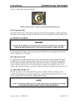
EVAPORATOR COIL
ICING UP
1. Lack of refrigerant
2. Restricted air or cold air re-circulated
3. Expansion valve not opened
sufficiently
4. Expansion valve power element
leaks
5. De-ice interval too long for that
particular site
6. Too much cold water to be heated
1.
Check for leaks. Repair and replace refrigerant.
2.
Proper clearance for air flow
3.
Check and adjust for proper superheat
4.
Replace expansion valve
5.
Shorten the de-ice interval
6.
Reduce the amount of water or add a head pressure
regulator to the machine
1. Compressor loses oil owing to
refrigerant flooding back
2. Compressor loses oil owing to
refrigerant leaks
3. System contaminated, and/or Liquid
injection capillary tube blocked
4. Suction superheat too high
5. Oil degrades owing to high
temperature
COMPRESSOR
THERMAL SWITCH
OPEN
6. De-icing could not de-ice completely.
7. Crankcase heater burned out
1.
Check and fix the flood back problem. Add oil if
necessary
2.
Find and repair the leakage. Add oil if necessary
3.
Purging the system and change oil and the filter/drier
4. Adjust
superheat
5.
Find and rectify the high discharge temperature. Change
the oil (to the requirement amount!) purge the system
and change the filter/drier
6.
Find and rectify the de-ice problem
7.
Replace crankcase heater
HIGH
DISCHARGE
PRESSURE
1. Non condensibles in system
2. Refrigerant overcharged
1.
Remove with authorized procedures
2. Remove
excess
charge
3. Water temp cut-out setting too high
3.
Check the settings
4. Condenser water tube scaled
4.
Clean the tube
5. Blocked condenser
5. Clean
condenser
6. Higher suction pressure than normal
6.
Refer to ‘High Suction Pressure’
1. Lack of refrigerant
1.
Check for leaks. Repair then replace refrigerant.
2. Evaporator dirty
2. Clean
evaporator
3. Clogged filter drier (pipe after the
filter cold)
3.
Replace filter drier
LOW SUCTION
PRESSURE
4. Expansion valve malfunctioning
(leakage phial/bulb)
4.
Check and change it
5. De-icing could not de-ice completely
5.
Check and adjust the de-icing setting if necessary.
UNSTABLE
SUCTION
1. Expansive valve hunting
1.
Check and close the valve for proper superheat
2. Ice-blocking in the expansion valve
(ice up in the Valve body)
2.
Check and change the refrigerant and the drier
PRESSURE
UNSTABLE
DISCHARGE
1. Non condensibles in system
1.
Remove with authorized procedures
2. Refrigerant overcharged
2. Remove
excess
charge
PRESSURE
COMPRESSOR
INTERVAL TOO
SHORT
1. Erratic water thermostat
1. Replace
sensor
2. Insufficient water flow
2. Adjust
flow
1. Low voltage during high loads
1.
Check supply voltage
MOTOR
2. Defective or grounded motor wiring
2. Replace
compressor
OVERLOAD
3. Loose power wiring
3.
Check all connections and tighten
RELAYS OPEN
4. High evaporating temperature
4.
See steps for high discharge
OR BLOWN
5. Liquid refrigerant flood back
5.
Too much refrigerant. Check the evaporator, the fan and
the TX valve opening.
FUSES
6. Unbalanced voltage
6.
Check voltage. Contact Power Company
Document Number : QDC0049PD-5
Page 29 of 33


