background image

quantum

M A S C H I N E N   -   G E R M A N Y

 ©

 200

7

GB

Page 1

18 / 01 / 2008

Version 1.2.5

B 13 / B14 / B16 / B20 / B25 / B32

Drilling machine

Bench drill

B 13
B 14
B 16
B 20 / B20 Vario

Operating manual

Version 1.2.5

Keep for future reference !

Pillar drill

B 25 / B 25 Vario
B 32 / B 32 Vario

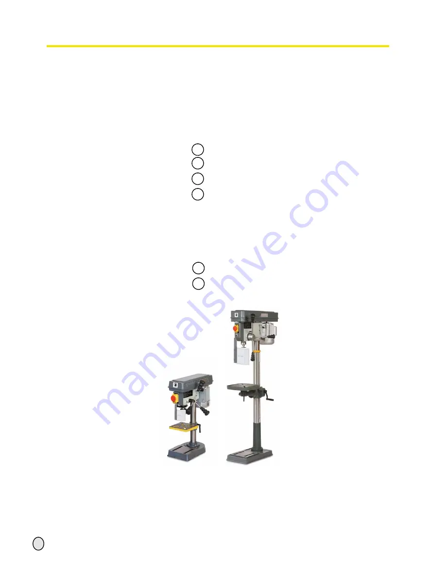
Illustr. 0-1:          B13                         B 25


Summary of Contents for B 13

Page 1: ...7 GB Page 1 18 01 2008 Version 1 2 5 B 13 B14 B16 B20 B25 B32 Drilling machine Bench drill B 13 B 14 B 16 B 20 B20 Vario Operating manual Version 1 2 5 Keep for future reference Pillar drill B 25 B 25...

Page 2: ...the pulleys 11 1 7 3 Prohibition warning and mandatory labels 11 1 8 Safety check 11 1 9 Personal protective equipment 11 1 10 Safety during operation 12 1 11 Safety during maintenance 12 1 12 Use of...

Page 3: ...B14 B16 B20 B25 B32 6 1 Ersatzteilzeichnung Parts drawing B13 B14 38 6 2 Bohrfutterschutz B13 B14 Drill chuck protection B13 B14 39 6 2 1 Ersatzteilliste Parts list B13 B14 39 6 3 Ersatzteilzeichnung...

Page 4: ...warning notes on the drilling machine European standards must be kept during installation operation maintenance and repair of the drilling machine If European standards are not applied at the nationa...

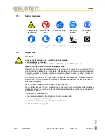
Page 5: ...ning danger that will cause serious injury or death to people WARNING Risk A danger that might cause serious injury or death to a person CAUTION Danger or unsafe procedure that might cause injury to p...

Page 6: ...s If the drilling machine is used in any way other than as described above modified without the authorisation of Optimum Maschinen GmbH or operated with different process data then it is being used im...

Page 7: ...ined by employees who are poorly qualified then there might be a risk resulting from incorrect operation and unsuitable maintenance of the drilling machine INFORMATION Everyone involved in the assembl...

Page 8: ...are working for the operator and for the manufacturer The operator must Obligations of the opera tor train the staff instruct the staff in regular intervals at least once a year on all safety standar...

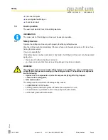
Page 9: ...safety device has been activated or has failed the drilling machine must only be operated again when the cause of the failure has been removed you have made sure that there is no existing danger for p...

Page 10: ...table there are holding fittings for sliding blocks WARNING There is danger of injury because of the parts flying off Tighten the workpiece properly into the drilling machine table Illustr 1 2 drilli...

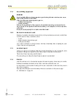
Page 11: ...defect or change in the operating function Check all safety devices at the beginning of each shift with the machine stopped once a week with the machine in operation after every maintenance and repair...

Page 12: ...not work on the drilling machine if your concentration is reduced for example because you are taking medication Observe the regulations for the prevention of accidents issued by your association for t...

Page 13: ...em once the work has been completed such as covers safety indications and warning signs earth ground cables If you remove protection or safety devices refit them immediately after completing the work...

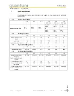
Page 14: ...rilling capacity B 13 B 14 B 16 B 20 B 25 B 32 drilling capacity in steel mm 13 14 16 20 20 32 reach mm 104 104 125 170 170 225 spindle sleve travel mm 50 50 65 80 80 125 2 3 Spindle holding fixture B...

Page 15: ...h mm 420 420 510 700 690 790 width mm 220 230 270 300 390 400 total weight kg 21 24 38 56 63 138 column diameter mm 46 46 60 70 70 92 2 6 Working area B 13 B 14 B 16 B 20 B 25 B 32 height mm 2050 2050...

Page 16: ...cient load capacity and that it is in perfect condition B13 B14 B16 B20 B20 Vario B25 B32 B25 Vario B32 Vario drilling head drilling head drilling head drilling head drilling table with pre mounted cl...

Page 17: ...ons Environmental conditions on page 15 Consult Optimum Maschinen GmbH if the drilling machine and accessories have to be stored for a period of over three monthes or under different external conditio...

Page 18: ...table Push the complete table with the toothed rack onto the tripod Illustr 3 2 Assembly of the drilling machine table B20 INFORMATION The larger part without toothing of the toothed rack must be ups...

Page 19: ...ush the drilling table support with mounted drilling table onto the column Illustr 3 6 Assembly drilling table B13 B14 Assembly of the drilling head Put the drilling head on the tripod and turn it unt...

Page 20: ...ling machine to the base using the holes in the stand The place where the drilling machine is installed must comply with ergonomic workplace require ments ATTENTION Tighten the setscrews on the drilli...

Page 21: ...e guarantee is null and void ATTENTION Drilling machines with frequency converter should not be operated with a CEE plug Con nect the machine permanently to a connection box see EN 50178 5 2 11 1 INFO...

Page 22: ...2 Drilling machine B 13 B14 B16 B20 B25 B32 Version 1 2 5 18 01 2008 3 5 1 Phase inverter for 400V machines Change the poles by means of the phase inverter if the turning direction of the drill ing ma...

Page 23: ...ivated All malfunctions should be eliminated immediately Stop the machine immediately at an event of any malfunction in operation and make sure it cannot be started up accidentally or without authoriz...

Page 24: ...e locking screw and turn the graduated collar until the required drill depth superimposes with the pointer Retighten the locking screw Illustr 4 3 Drill depth stop B16 B32 pulley drive with housing ha...

Page 25: ...drilling machine table can be inclined to the right or to the left Loosen the fastening screws For B16 B20 B25 B32 Pull out the threaded pin Illustr 4 5 Fastening screw INFORMATION If the threaded pi...

Page 26: ...d push the motor in direction of the drill chuck Type Vario Adjust the required speed with the potentiometer Depending on the position of the V belts on the V belt pulleys you will get a certain speed...

Page 27: ...01 2008 Version 1 2 5 B 13 B14 B16 B20 B25 B32 Drilling machine 4 3 1 Speed table Speed table B13 B14 Illustr 4 7 Speed table quantum B13 B14 Speed table B16 Illustr 4 8 Speed table quantum B16 2435 s...

Page 28: ...N G E R M A N Y 2007 GB Page 28 Drilling machine B 13 B14 B16 B20 B25 B32 Version 1 2 5 18 01 2008 Speed table B20 B25 Illustr 4 9 Speed table B20 B25 spindle 533 376 268 796 453 323 1029 1274 516 178...

Page 29: ...B16 B20 B25 B32 Drilling machine Speed table B20 Vario B25 Vario Illustr 4 10 Speed table B20 Vario B25 Vario spindle 526 371 264 785 447 318 1014 1256 509 1757 2177 1239 engine center pulleys 1367 96...

Page 30: ...M A S C H I N E N G E R M A N Y 2007 GB Page 30 Drilling machine B 13 B14 B16 B20 B25 B32 Version 1 2 5 18 01 2008 Speed table B32 Speed table B 32 spindle 379 288 167 1368 585 339 1106 1970 489 engin...

Page 31: ...1349 576 335 1090 1942 482 engine center pulleys 15 100 225 970 739 429 3507 1498 870 2835 3500 1253 22 17 10 81 35 20 65 117 29 material drill diameter cooling 3 2 3 4 5 6 7 8 9 10 steel unalloyed up...

Page 32: ...ed during the drilling process Cooling the tool with a suitable cooling lubricant ensures better working results and a longer edge life of the tools This is best realized by a separate cooling equipme...

Page 33: ...tive mask for any work which generates dust 4 8 During the working process The spindle sleeve feed is being performed by the star grip Make sure that the feed is being at a regular pace and not too fa...

Page 34: ...n optimum condition ENVIRONMENTAL PROTECTION During work on the spindle nose and the apron make sure that collector vessels are used with sufficient capacity for the amount of liquid to be col lected...

Page 35: ...1 1 Preparation WARNING Only carry out work on the drilling machine if it has been switched off using the main switch and secured with a padlock to prevent the machine from being turned on Attach a wa...

Page 36: ...Checking the tension of the V belts Speed alternation on page 26 Illustr 5 2 B20 drilling head on the right every month tripod and rack lubricate Lubricate the tripod regularly with commercial oil Lu...

Page 37: ...echnical staff they must follow the indications given in this manual Optimum Maschinen GmbH does not take responsiblity nor does it guarantee against damage and operating malfunctions resulting from f...

Page 38: ...antum M A S C H I N E N G E R M A N Y 38 S Betriebsanleitungen drilling_machines B13_14_16_20_25_32 B13 B32_parts B13 B32_parts fm 18 1 08 6 Ersatzteile Spare parts B13 B14 B16 B20 B25 B32 6 1 Ersatzt...

Page 39: ...08 9 Federscheibe Spring Washer 1 M 12 10 Bohrtisch Work Table 1 0300813110 11 Bohrtischhalter Support 1 0300813111 12 Bolzen Bolt 1 M6x25 13 Mutter Nut 1 M6 14 Getriebeachse Gear Axis pinion shaft 1...

Page 40: ...Kugellager Bearing 1 6201 0406201 2R 69 Gummiunterlegscheibe Rubber Washer 1 0300813169 70 Pinole Pinole 1 0300813170 71 Kugellager Bearing 1 6201 0406201 2R 72 Spindel Spindle 1 0300813172 73 Bohrfut...

Page 41: ...E N G E R M A N Y Ersatzteile Spare parts B13 B14 B16 B20 B25 B32 18 1 08 S Betriebsanleitungen drilling_machines B13_14_16_20_25_32 B13 B32_parts B13 B32_parts fm 41 6 3 Ersatzteilzeichnung Parts dra...

Page 42: ...110 11 Schraube Screw 1 M5x10 12 Bolzen Bolt 1 0300816112 13 Klemmhebel Clamp Handle 1 0300816113 14 Zahnrad Gear 1 0300816114 15 Schneckenrad Gear Wheel 1 0300816115 16 Bohrtisch Work Table 1 0300816...

Page 43: ...0300816170 71 Kugellager Bearing 1 6201 0406201 2R 72 Gummiring Rubber ring 1 0300816172 73 Pinole Pinole 1 0300816173 74 Austreiber Drill Drift 1 0300816174 75 Kugellager Bearing 1 6205 0406205 2R 76...

Page 44: ...B14 B16 B20 B25 B32 quantum M A S C H I N E N G E R M A N Y 44 S Betriebsanleitungen drilling_machines B13_14_16_20_25_32 B13 B32_parts B13 B32_parts fm 18 1 08 6 5 Ersatzteilzeichnung Parts drawing B...

Page 45: ...ohrtischhalter Support 1 0300820109 10 Kurbel Crank 1 0300820110 11 Schraube Screw 1 M 6x15 12 Getriebewelle Gear Shaft 1 0300820112 14 Schraube Screw 1 M 6x15 15 Klemmhebel Clamp Handle 1 0300820115...

Page 46: ...6201 0406201 2R 62 Keilriemen V belt 1 10 x 610 0300820162 63 Riemenscheibe Mitte Middle Pulley 1 0300820163 64 Zentrierteil Centering Device 1 0300820164 65 Hebel Lifting Handle 1 0300820165 66 Riem...

Page 47: ...203 1 Endlagenschalter Bohrfutterschutz End position switch drill chuck protec tion 1 030081312031 205 Geh use Trafo Housing trafo 1 03008201205 Teile ohne Abbildung Parts without illustration 0 Kond...

Page 48: ...B13 B14 B16 B20 B25 B32 quantum M A S C H I N E N G E R M A N Y 48 S Betriebsanleitungen drilling_machines B13_14_16_20_25_32 B13 B32_parts B13 B32_parts fm 18 1 08 6 7 Ersatzteilzeichnung Parts drawi...

Page 49: ...zen Pin 1 0300832317 18 Schneckenrad Worm Wheel 1 0300832318 19 Kurbel Crank 1 0300832319 20 Schraube bolt 1 M 6 x 12 21 Zahnrad Gear 1 0300832321 23 S ulenring Column Ring 1 0300832323 24 Klemmhebel...

Page 50: ...ss Wire Block 2 0300832376 77 Scheibe Washer 2 0300832377 78 Bolzen Bolt 2 0300832378 79 Bolzen Bolt 1 M5x8 80 Quardatisches Bord Square Board 1 0300832380 81 Scheibe Washer 4 6 82 Federring Spring Wa...

Page 51: ...uck protection 1 03008201203 203 1 Endlagenschalter Bohrfutterschutz End position switch drill chuck protec tion 1 030081312031 205 Geh use Trafo Housing trafo 1 03008323205 Teile ohne Abbildung Parts...

Page 52: ...0 B25 B32 quantum M A S C H I N E N G E R M A N Y 52 S Betriebsanleitungen drilling_machines B13_14_16_20_25_32 B13 B32_parts B13 B32_parts fm 18 1 08 6 9 Schaltplan Wiring diagram B13 B20 230V 6 10 S...

Page 53: ...E N G E R M A N Y Ersatzteile Spare parts B13 B14 B16 B20 B25 B32 18 1 08 S Betriebsanleitungen drilling_machines B13_14_16_20_25_32 B13 B32_parts B13 B32_parts fm 53 6 11 Schaltplan Wiring diagram B...

Page 54: ...ecured Drill chuck defective Replace bit Have the bearings replaced Secure the bit properly Replace the drill chuck Impossible to introduce drill chuck or morse taper There is dirt grease or oil on th...

Page 55: ...roller bearings Reduce drilling revolutions feed Ratteling of the working spindle when working with rough workpiece surfaces Clearance of the bearing too wide The working spindle moves up and down The...

Page 56: ...inology Glossary Term Explanation drill drift tool to release the bit or the drill chuck from the drill spindle drill chuck drill holding fixture drilling head upper part of the drilling machine drill...

Page 57: ...n of a third party any warranty claim will expire Maintenance work and cle aning are usually not part of the claim of warranty Original spare parts Make sure to use only original spare parts and origi...

Page 58: ...a follow up service for our products which extends beyond shipment We would be grateful if you could send us the following information modified settings experiences with the drilling machine which co...

Page 59: ...B20 B20 Vario B25 B25 Vario B32 B32 Vario relevant EU directives machine directives 98 37 EG Appendix II A EMV directive 89 336 EWG low voltage directive 73 23 EWG meets the provisions of the aforemen...

Page 60: ...conditions 15 Extent of supply 16 H Handling 23 I Inclination of the drilling machine table 25 Inspection 35 Installation 17 Installation drawings 20 M Maintenance 34 Malfunctions 54 O ON OFF switch 1...

Reviews: