Installing the DXi4700 System in the Rack
Quantum DXi4700 Installation Guide
49
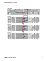
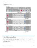
1. Connect each Array module (RBOD) to the DXi4700 Node.
l
).
l
).
Table 1:
Connecting the DXi4700 G1 Expansion Modules (JBODs)
Node
JBOD 1
JBOD 2
JBOD 3
SAS port 1
(left)
Primary SAS In port (top)
SAS port 2
(right)
Secondary SAS In port
(bottom)
Primary SAS Out port (top)
Primary SAS In port (top)
Secondary SAS Out port
(bottom)
Secondary SAS In port
(bottom)
Primary SAS Out port (top)
Primary SAS In port (top)
Secondary SAS Out port
(bottom)
Secondary SAS In port
(bottom)
Table 2:
Connecting the DXi4700 G2 Expansion Modules (JBODs)
Node
JBOD 1
JBOD 2
JBOD 3
SAS port 1 (left)
Primary SAS In port 1 (top)
SAS port 2
(right)
Secondary SAS In port 1
(bottom)
Primary SAS port 2 (top)
Primary SAS port 1 (top)
Secondary SAS port 2
(bottom)
Secondary SAS port 1
(bottom)
Primary SAS port 2 (top)
Primary SAS port 1 (top)
Secondary SAS port 2
(bottom)
Secondary SAS port 1
(bottom)
2. Do
not
connect any Ethernet cables at this time. (You will connect them in a later procedure.)
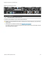
3. (VTL and Multi-Protocol configurations only) Connect Fibre Channel cables to each Fibre Channel port
). Fibre Channel ports 0 and 1 are used for virtual tape library (VTL)
host connection.
4. (Multi-Protocol only) Connect Fibre Channel cables to each Fibre Channel port in slot 2 (see
). Fibre Channel ports 2 and 3 are used for Path-to-Tape (PTT) connections.


