11
Installation
B
1
B
2
L
N
N
L
E
Boost Switch
Permanent Supply [Peak Supply]
Switched Switch [Off Peak Supply]
Switched Supply
[Off Peak Supply]
Permanent Supply
[Peak Supply
]
16A MCB
16A MCB
Kitchen
Airing Cupboard
Note:
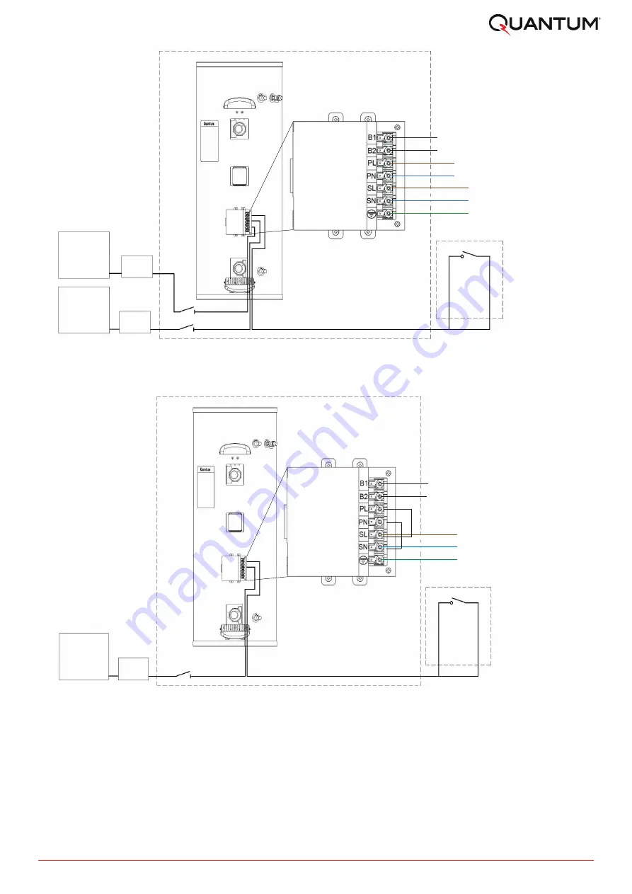
The Boost connections must be connected in series with a toggle switch which allows the external boost function to be utilised.
The external boost connection on the Quantum cylinder is a contact wire which must not be connected to the mains power supply.
If an electronic timer switch from a previous installation is in place it must be replaced with a single pole toggle switch which is
wired from the B1 and B2 connections as shown in Figure 7.
The water temperature required from the boost function can then be set from the UI and the boost element will automatically turn
off once this temperature is achieved in 55 litres of the water stored.
When connected to a permanent supply, the charge period must be programmed on the cylinder user interface, see Section 7.
Figure 7: Off Peak Wiring Configuration
B
1
B
2
Boost Switch
N
L
E
Permanent Supply [Peak Supply]
Permanent Supply/
Peak Supply
16A MCB
Boost Switch
Kitchen
Airing Cupboard
Figure 8: Energised or Always On Wiring Configuration
6.5.2
Wiring Configurations
Summary of Contents for IOT Series
Page 12: ...12 Installation Figure 9 Wiring Schematic...
Page 31: ...31 Notes...
Page 32: ...32 Notes...
Page 33: ...33 Notes...


