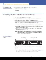
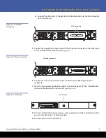
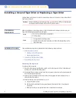
background image

4

Installing a Second Tape Drive or Replacing a Tape Drive

LTO-3 (Model B), LTO-4 (Model B), LTO-5, LTO-6 and LTO-7

Installing a Second Tape Drive or Replacing a Tape Drive

Follow these instructions to install a second tape drive or to replace a tape drive after it 
has been removed. 

Caution:

Before installing a second tape drive, you must turn off the 1U Rackmount 

enclosure and disconnect it from its AC power source.

Preinstallation 

Requirements

Before installing a second tape drive in the 1U Rackmount enclosure, make sure you 
have the following required tools and parts:

Installation Procedure

The installation procedure is divided into the following major sections:

Removing the Top Panel

Adding a Second Tape Drive

Replacing a Tape Drive:

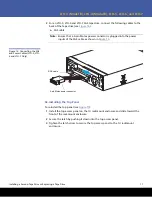
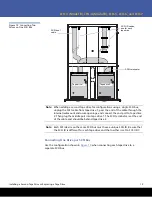
Connecting the Tape Drive Cables

Re-installing the Top Panel

Removing the Top Panel

To remove the top panel:

1

Press the drive power pushbutton switch on the front panel of the 1U Rackmount 
enclosure to turn off the drive power.

2

Disconnect the AC power cable from the AC power connector on the back panel of 
the 1U Rackmount enclosure.

3

Remove the 1U Rackmount enclosure from the equipment rack and place it on a 
clean, stable, flat surface. 

4

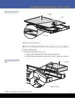
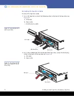
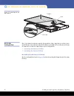
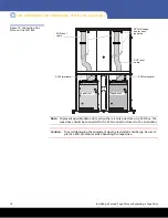
Remove the top access panel (see 

Figure 5

):

a

Loosen the latch screw

b

Lift the latch and slide the top panel toward the back of the 1U rackmount 
enclosure.

c

Remove the top access panel from the 1U rackmount enclosure.

Tools

3/16 in. (5 mm) flat-blade screwdriver
T-15 Torx driver

Parts

• A supported model tape drive
• Parallel SCSI cable and terminator or SAS cable depending on the 

tape drive type

Summary of Contents for LTO-3 Model B

Page 1: ...ives already installed LTO 3 Model B Half Height SCSI model TC L33CX EY B LTO 3 Model B Half Height SAS model TC L33CN EY B LTO 4 Model B Half Height SCSI model TC L43CX EY B LTO 4 Model B Half Height...

Page 2: ...b Connect the other end of the supplied external parallel SCSI cable to the parallel SCSI connector on the host server c As required use the parallel SCSI ID selector switch to set the SCSI ID of the...

Page 3: ...he 1U Rackmount enclosure see Figure 3 Figure 3 AC Power Connector 6 Connect the other end of the AC power cable to the rack facility AC power receptacle 7 Press the drive power pushbutton switch on t...

Page 4: ...Adding a Second Tape Drive Replacing a Tape Drive Connecting the Tape Drive Cables Re installing the Top Panel Removing the Top Panel To remove the top panel 1 Press the drive power pushbutton switch...

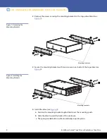
Page 5: ...are replacing a tape drive refer to Replacing a Tape Drive on page 7 To add a second tape drive 1 Remove the drive blank see Figure 6 a Pull the spring loaded button on the right mounting rail up b Sl...

Page 6: ...ng the Mounting Brackets 3 Secure the mounting brackets with two screws on each side of the tape drive see Figure 8 Figure 8 Installing the Mounting Brackets 4 Install the drive see Figure 9 a Positio...

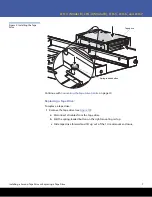
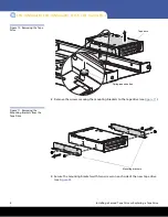
Page 7: ...nue with Connecting the Tape Drive Cables on page 10 Replacing a Tape Drive To replace a tape drive 1 Remove the tape drive see Figure 10 a Disconnect all cables from the tape drive b Pull the spring...

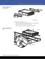
Page 8: ...10 Removing the Tape Drive 2 Remove the screws securing the mounting brackets to the tape drive see Figure 11 Figure 11 Removing the Mounting Brackets from the Tape Drive 3 Secure the mounting bracket...

Page 9: ...e Mounting Brackets 4 Install the new tape drive see Figure 9 a Position the mounting bracket keyhold slots over the mounting posts b Slide the drive toward the back of the enclosure c The spring load...

Page 10: ...to the back of the tape drive see Figure 14 a SCSI cable b Power cable c SCSI ID selector switch Figure 14 Connecting the SCSI and Power Cables 2 For an LTO 3 Model B and LTO 4 Model B SAS tape drive...

Page 11: ...the power inputs of the SAS cable as shown in Figure 16 Figure 16 Connecting the SAS and Power Cables LTO 5 LTO 6 and LTO 7 Only Re installing the Top Panel To re install the top panel see Figure 17...

Page 12: ...operation of two tape drives on either one or two SCSI buses Two internal 2 port SCSI cables are installed in the enclosure and ready for tape drive connections depending on your configuration Connec...

Page 13: ...d connect the end port to tape drive 2 Then plug the middle port into tape drive 1 The SCSI terminator is at the end of the cable and should be behind tape drive 2 Note Each SCSI device on the same SC...

Page 14: ...when there is only one drive on a SCSI bus the tape drive should be connected to the SCSI connector closest to the terminator Caution To avoid damaging the equipment due to electrostatic discharge be...

Page 15: ...Mounting Kit Components Tools Required If you are installing the tape enclosure in a rack with unmarked holes in the vertical mounting bars the following items will make the rack installation easier P...

Page 16: ...more than one component is extended for any reason Before you begin If you are installing the 1U rackmount enclosure in a rack with unmarked holes in the vertical mounting bars identify and mark the...

Page 17: ...eaded holes the mounting pins must first be removed Refer to the following sections for installation instructions for your rack type Installing in a Rack with Round or Square Holes Installing in a Rac...

Page 18: ...rails for repositioning push the spring loaded tab on the outside of the rack rail and slide it forward 2 Extend the rack rails past the rear vertical mounting bar and insert the pins in the mounting...

Page 19: ...rward The rail installation is complete Continue with Completing the Installation on page 22 Installing in a Rack with 10 32 in Threaded Holes For installation in racks with 10 32 threaded holes in th...

Page 20: ...e 24 Removing the Pins from the Rack Rails Note The ends of the rack rails are marked FRONT and REAR for proper orientation 2 Attach the front mounting plate of each outer rail to the rack using four...

Page 21: ...of the Rack 3 Extend the rack rails past the rear vertical mounting bars and attach the back mounting plate of each outer rail to the rack using four 10 32 screws in the previously marked holes see F...

Page 22: ...into the rack see Figure 27 Figure 27 Sliding the 1U Rack Enclosure into the Rack Caution Be sure to keep the enclosure parallel to the floor when sliding the component rails into the rack rails Tilt...

Page 23: ...lied external SAS interface cable to the external SAS interface connector on the same side of the enclosure as the installed tape drive see Figure 2 b Connect the other end of the external SAS interfa...

Page 24: ...long standing and trusted partner the company works closely with a broad network of resellers OEMs and other suppliers to meet customers evolving data protection needs 6 66789 03 24 6 66789 04 Rev A D...

Reviews: