50 Chapter 7 Operation of 5U enclosures
Remove power from the 5U enclosure
The storage enclosure relies on main power provided through separate, independent power distribution. If you
lose main power for any reason, the storage enclosure automatically restarts after power restoration.
You must quiesce all data exchange before removing power to the storage enclosure.
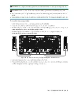
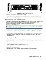
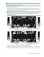
To remove power from the 5U enclosure:
CAUTION Never remove power from a redundant power supply unit (PSU) when the other PSU has a
fault condition, indicated by an amber LED.
1. After you complete the proper shut down of the application and when you are ready to power down the
storage enclosure, press the power switch to the OFF position for each PSU.
2. Disconnect each power connector from its PSU socket or from the PDU.
3. You must wait a minimum of 15 seconds before power cycling the PSU and a minimum of 30 seconds after
successful completion of the power on sequence before you attempt to place the PSU in standby or remove
power again.
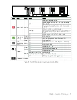
Interpret system LEDs
Visual cues provide you with the means to monitor the storage enclosure and its components and reinforce
software messages about system health. Use LEDs throughout the storage enclosure to determine if there is a
critical fault.
The storage enclosure registers the following states using the identified LED colors.
1. Green or unlit LED: Indicates a module is functioning normally
2. Flashing green or amber LED: Indicates a non-critical condition
3. Amber LED: Indicates a critical fault
4. Blue LED: Indicates system component identification, so is not a fault or critical condition
Since an amber fault LED uses fast or slow flashes to cover multiple conditions, this is the priority for
simultaneous indications:
Priority
Flash rate
Indication
Description
Top priority
Fast flash (1s on, 1s
off)
Identify
Locate the enclosure or module
Priority 2
On
Fault
Fault condition detected
Priority 3
Slow flash (3s on, 1s
off)
Logical or non-critical fault Logical fault or non-critical notification
Lowest priority Off
No indication
System functioning normally
Table 4 Fault LED prioritization
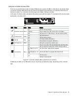
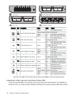
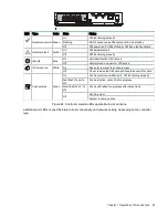
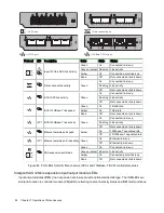
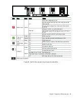
The front panel area, controller module, and expansion module LEDs require further elaboration.
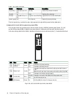
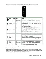
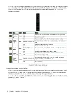
Interpret 5U enclosure operator's panel LEDs
The storage enclosure operator's (ops) panel contains a series of LEDs to reflect system status. You can
monitor the ops panel LEDs to determine system status in combination with the user interface content.

