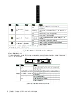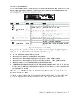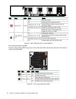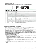
Chapter 9 Hardware installation and configuration issues
81
2. Alerts fall into three categories, listed in order of severity. Resolve them, moving from most severe to least
severe.
a. Critical alerts: Such alerts require immediate resolution, since they may cause a controller module to
shut down or place data at risk.
b. Warnings: Such alerts require immediate attention so you can evaluate the problem and correct it.
c. Informational alerts: Such alerts neither require immediate attention nor immediate action.
3. Use the Disk Storage Management Utility (DSMU). You can use the DSMU to monitor the health icons or
values for the system and its components, to make sure that everything is functioning properly, or to locate
a problem component.
4. Use the command line interface (CLI). If you discover a problem, review both the DSMU and the CLI for any
recommended actions.
5. Visually inspect front panel fault LEDs, then locate component fault LEDs, based on LED-identified general
location. If a hardware issue prevents access to the DSMU or CLI, it is the only option available.
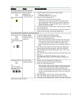
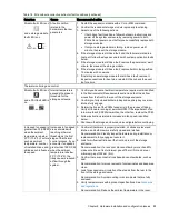
Symptom
Cause
Recommended Action
Operator's panel area LEDs, no fault conditions
System power, system ID, and host
connectivity LEDs with no module, logical, or
drawer fault LEDs
System functioning properly
No action required.
Drawer panel LEDs, no fault conditions
Drawer power and sideplane OK LED
System functioning properly
No action required.
Drawer data activity bar
Drive module LEDs, no fault conditions
Amber flashing LED: 1 second on, 1 second off Drive unit identification (UID) bit is
set
No action required.
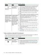
Controller or expansion module LEDs, no fault conditions
LEDs other than:
-CM amber fault LEDs
-SAS port amber fault LEDs
System likely functioning properly
Often, no action required. See
"Interpret controller module LEDs"
on page 52
FCM LEDs, no fault conditions
FCM OK amber LED flashing
PCM is in standby mode
No action required.
PSU LEDs, no fault conditions
PSU OK amber LED flashing
PCM is in standby mode
No action required.
Table 14 5U enclosure non-fault conditions
Isolate hardware and connectivity faults
You may occasionally have to isolate a fault related to the storage enclosure hardware or related to data
connections associated with the enclosure. This is particularly true with data paths because of the number of
components involved along the data path and the complexity of the interactions. For example, if a host-side
data error occurs, it could be caused by any of the involved hardware components. It could be on the host side,
such as a faulty host bus adapter (HBA) or switch. It could be on the storage enclosure side, such as a faulty
controller module (CM), cable, or connector. It also could be a failure involving more than one of these
components.
Use this section to gather common installation hardware fault information and isolate the fault.


