198
Configuring the Library
Configuring FC Host Port Failover
Configure the optional FC Host Port Failover (HPF) feature so that an alternate “standby” target port on an
I/O blade can assume the identity and LUN mapping configuration of the primary “active” target port if the
primary port fails. HPF enables the library to continue operations without requiring you to reconfigure the
host or the SAN.
To enable HPF, you must make sure that two ports on the I/O blade are in target mode and point-to-point
connection. Use ports 1 and 2, which are ports that are traditionally configured to be host targets. I/O blade
ports are numbered from bottom to top as the blade sits in the I/O management unit.
Both ports must be attached to the same SAN fabric to provide host access. The active primary port is used
for host communications, while the passive standby port is kept idle. The way that you configure the
recovery settings determines how the failed port behaves after it is restored from a failed state.
The library generates a ticket when port failover occurs. Examine the ticket and the repair page associated
with the ticket to determine the reason for the failover.
To configure HPF, perform the following steps:
1
Log on as an administrator.
2
Make sure that you are viewing the physical library. From the
View
menu, click the name of the physical
library.
3
Confirm that there are two ports on the I/O blade in target mode and point-to-point connection. For more
information, see "FC Host" in the
Scalar® i6000 User’s Guide
.
4
Click
Setup
→
Connectivity
→
FC Host Port Failover
.
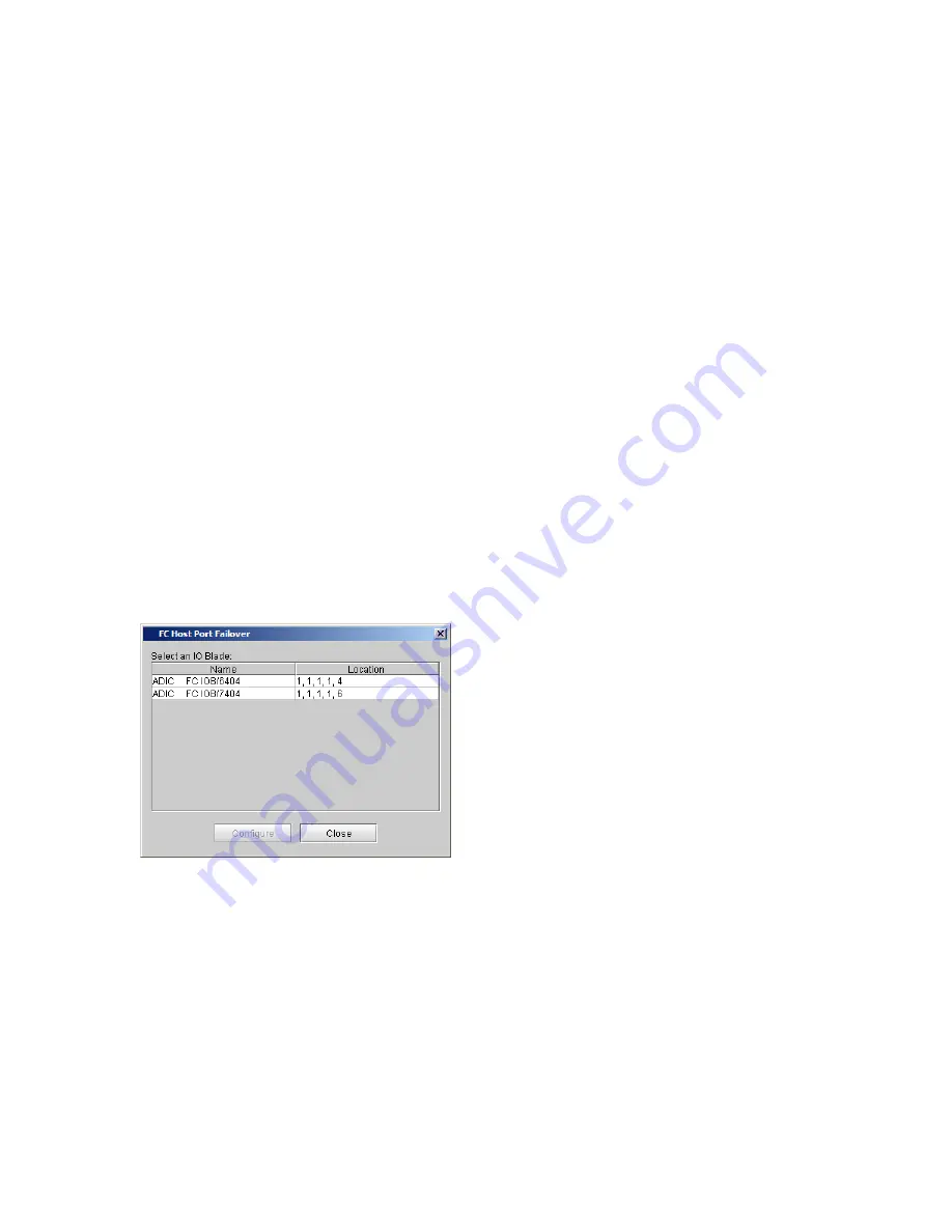
The
FC Host Port Failover
dialog box appears, showing all the I/O blades found in the library. Each
blade is identified by name and by location.
Summary of Contents for Scalar i6000
Page 20: ...8 About This Guide and Your Product...
Page 38: ...26 Installing a Stand Alone Control Module...
Page 104: ...92 Installing a Multi Module Library...
Page 156: ...144 Installing Cartridges...
Page 164: ...152 Setting up Your Library for Access...
Page 242: ...230 Configuring the Library...
Page 304: ...292 Adding Optional Hardware eight 2 5 mm screws...
Page 318: ...306 Adding Optional Hardware...
Page 336: ...324 Installation Testing and Verification Figure 35 Example Test Log Output...
Page 356: ...344 Testing and Calibrating the Digital Level...
Page 362: ...350 LBX Board and Terminator...
Page 380: ...368 Glossary...
Page 384: ...372 Index...


