238
Adding Optional Hardware
.
20
Use the #2 Phillips screwdriver or your fingers to tighten the two retaining thumbscrews of the UDS drive
sled.
21
Add any additional tape drives in the lower drive cluster. When the lower cluster is full, add the next tape
drive to the upper drive cluster.
22
Verify that the green LED on the back of the drive is on. If it is not on, the drive is not installed properly.
23
Observe the state of the green LED while the drive sled firmware automatically loads. It could take up
to 20 minutes to complete the drive sled firmware download. When the green LED is solid on for three
seconds, then blinks twice and repeats, the drive firmware is downloading. The drive sled firmware
download is complete when the green LED blinks one time every second, the amber LED is off, and the
blue LED blinks one time every 10 seconds. See
Interpreting Drive Status LEDs
complete listing of the LED blinking codes.
24
Use the instructions in
on page 111 to connect the new drives.
25
Detach the ESD strap and close the door.
The power is on.
26
From the LMC, click
Tools
→
Teach
.
27
Click
Configure,
and then click
Start
.
Note
•
After you add a drive, the robotics control unit ensures that the drive
sled is loaded with the proper firmware. This firmware is based on the
currently installed level of library firmware on the management control
blade (MCB). If the autoleveling process fails, the drive sled becomes
inoperable and the library creates a ticket to report the issue.
•
If more than one drive is added into the library, when the library is
already powered up, the RCS autolevels the drive after approximately
30 seconds. The autolevel countdown restarts if another drive is added
within 30 seconds of the last added drive. The RCS queues up all drives
inserted before performing the autolevel.
•
Because UDS-2 and UDS-3 sleds require different application images,
if your library contains both types of sleds, the RCS may need to
autolevel twice.
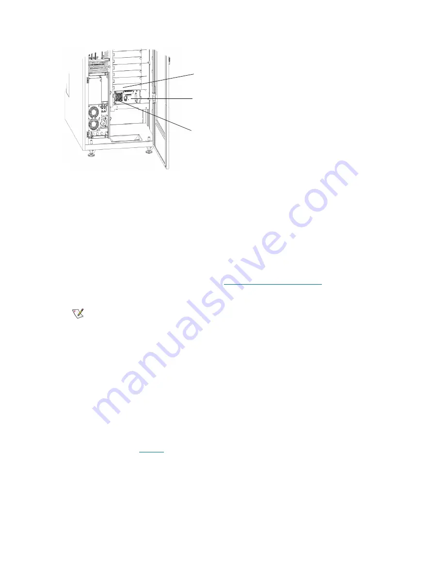
cover plate
drive
glide rail
Summary of Contents for Scalar i6000
Page 20: ...8 About This Guide and Your Product...
Page 38: ...26 Installing a Stand Alone Control Module...
Page 104: ...92 Installing a Multi Module Library...
Page 156: ...144 Installing Cartridges...
Page 164: ...152 Setting up Your Library for Access...
Page 242: ...230 Configuring the Library...
Page 304: ...292 Adding Optional Hardware eight 2 5 mm screws...
Page 318: ...306 Adding Optional Hardware...
Page 336: ...324 Installation Testing and Verification Figure 35 Example Test Log Output...
Page 356: ...344 Testing and Calibrating the Digital Level...
Page 362: ...350 LBX Board and Terminator...
Page 380: ...368 Glossary...
Page 384: ...372 Index...


