62 Trinity F90+ user manual
Take-Off /Landing – Retransition
Retransition Waypoint
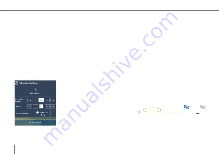
During the retransition the UAV will switch from aero fixed wing mode to hover mode. The retransition waypoint is the location
at which the UAV finishes the retransition. At this location the UAV is in hover mode. The retransition track is indicated by the
dotted path and is by default 150 m (492 ft).
• The retransition waypoint should be located close to the home waypoint (take-off and landing location) (ideal <50 meters; max.
100 meters). The distance between the two waypoints is covered in high energy demanding hover mode.
• Depending on the wind condition, the real retransition location might not comply with the retransition waypoint in QBase.
• If there are obstacles in an area with a radius of 50 meters (164 ft) around the retransition waypoint, make sure that the
retransition altitude is 20 meters (65.6 ft) higher than the obstacles are.
• Select the
Take-Off
or the
Retransition location
on the map or select
Take-Off/Landing
in the left section in order to set the
waypoint settings.
Retransition Altitude ATO (above take-off)
Defines the hover altitude at the end of the retransition. If the flight area allows for it, set the re
-
transition altitude as low as possible in order to save energy by reducing the hover duration to a
minimum.
~20 m deviation
per 1m/s tailwind
Example: Tailwind
Retransition
Waypoint
Direction
• It is recommended to set the direction
against the wind direction.
• In case it is not possible to carry out
the retransition against the wind direction, be aware that the real retransition location does
not match the retransition waypoint that was set in QBase (per 1 m/s tailwind ~ 20 meter
deviation).
• If there is an obstacle in the retransition track, make sure the retransition altitude is 20
meters (65.6 ft) higher than the obstacle.
Summary of Contents for Trinity F90+
Page 5: ...5 General information GENERAL INFORMATION 01...
Page 9: ...02 9 SAFETY INSTRUCTIONS Safety instructions...
Page 13: ...13 TECHNICAL SPECIFICATIONS 03 Technical specifications...
Page 17: ...17 04 PROCESS OVERVIEW Process overview...
Page 19: ...19 Trinity F90 user manual Flight operation After the ight Data Analysis Process overview 4...
Page 20: ...20 Trinity F90 user manual...
Page 21: ...21 COMMUNICATION LINKS 05 Communication links...
Page 23: ...23 BATTERY RC TRANSMITTER Battery RC Transmitter 06...
Page 36: ...36 Trinity F90 user manual...
Page 37: ...37 07 QBASE GROUND CONTROL STATION QBase Ground Control Station...
Page 51: ...51 Trinity F90 user manual...
Page 66: ...66 Trinity F90 user manual...
Page 84: ...84 Trinity F90 user manual...
Page 85: ...85 FLIGHT SETUP STEP BY STEP 08 Flight setup step by step...
Page 90: ...90 Trinity F90 user manual 8 11 Step 11 Assemble the UAV...
Page 94: ...94 Trinity F90 user manual...
Page 95: ...95 FLIGHT OPERATION 09 Flight operation...
Page 107: ...107 AFTER THE FLIGHT 10 After the flight...
Page 111: ...111 11 PAYLOAD COMPARTMENT Payload compartment...
Page 129: ...129 Trinity F90 user manual RX1RII Menu default settings 11...
Page 130: ...130 Trinity F90 user manual...
Page 137: ...137 STORAGE 12 Storage...
Page 139: ...139 INSPECTION REPAIRS 13 Inspection repairs...
Page 151: ...151 14 TROUBLESHOOTING Troubleshooting...
Page 161: ...161 FLYING MULTIPLE UAV SIMULTANEOUSLY 15 Flying multiple UAV simultaneously...
Page 163: ...163 iBASE FILE NAMES 16 iBase file names...
Page 166: ...166 Trinity F90 user manual...
Page 167: ...167 Trinity F90 user manual...


