


Torridon HS Lite Drive Control Module - Technical Manual
Revision 1.0
©Quarch Technology
Page 25 of 28
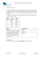
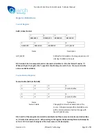
Source Registers
Each source is setup by a block of 9 16-bit wide registers. Below is the register map for a generic
source. The list of registers in the title indicates the actual address of the byte in each of the 6 timed
sources.
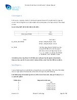
Source Delay [0x07, 0x18, 0x29, 0x3A, 0x4B, 0x5C]
7
6..0
DELAY_MULTIPLIER
DELAY
Name
Description
Sx_DELAY_MULTIPLIER
When 0, Delay Multiplier is 1mS
When 1, Delay Multiplier is 10mS
Sx_DELAY
The Total delay after HOT_SWAP is set (by
issuing RUN:POWer UP) until the signals
attached to this source beginning to mate
T
DELAY
= xV_DELAY x xV_DELAY_MULTIPLIER
i.e. 00000010 = 2mS, 10001001 = 90mS
Initial delay values range from 0 to 1270mS when set by writing the register value directly.
However, if you use the “source:n:delay” command then values from 0 to 9999 are available.
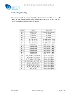
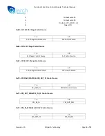
Signal Registers
Two switched signals are controlled by each signal byte, one in each nibble. The 4 bits of the nibble
stores a single number that describes which source the signal should be following.
Each nibble assigns the named signal to one of the six control sources, always off, always on, or
on with HOT_SWAP:
Nibble Value
Assigned Control Source
0
OFF
1
Follow Source S1
2
Follow Source S2
3
Follow Source S3
4
Follow Source S4


