QK-A015-RX Manual
V1
3 of 4
2020
3. Installation
The A015-RX is a plug and play device. No Configuration required.
IMPORTANT: Connect the VHF antenna BEFORE connecting any other devices!
Connecting powered devices to a Splitter before connecting the VHF antenna will damage your
devices.
1. Remove power source from all devices to be connected.
2. Connect the VHF antenna to the Splitter before adding any devices.
3. After the VHF antenna is connected, connect the VHF radio, AIS receiver and FM/AM radio to
the A015-RX Splitter.
4. Re-power all devices.
5. Test use checking status LEDs light up when expected.
4. Status LEDs
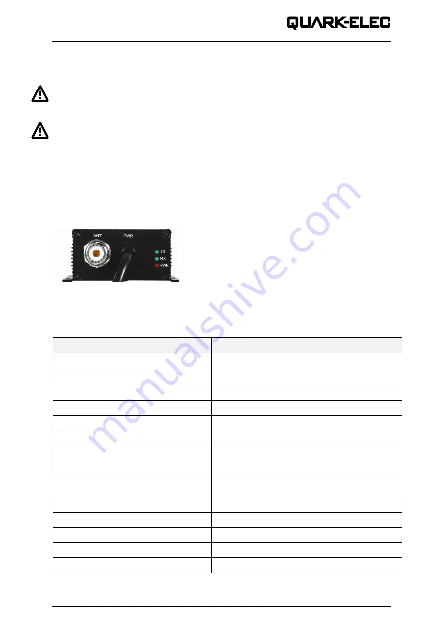
The A015-RX has three LEDs that indicate power and working status.
The VHF fail-safe means that the VHF radio has full priority and will remain functional, even in the
unlikely case that the Splitter would fail or lose power.
5. Specifications
Item
Specification
DC supply
9.0V to 35V
Average supply current
135mA
VHF and AIS frequency range
156MHz to 163MHz
AM/FM frequency range
0.5-1.6/88-108Mhz
VHF receive gain
Typical 12dB
AIS receive gain
Typical 12dB
FM/AM receive gain
Typical 10dB
Insertion loss VHF transmit paths
≤1.5dB
Max input Power from VHF port
25W when VHF antenna is connected. The antenna
must be connected before the VHF radio.
FM port impendence
75 Ohms
AIS, VHF and antenna port impedance
50 Ohms
Switching time, receiver to VHF transmit
<2ms
Operating temperature
-10°C to +55°C
Storage temperature
-25°C to +85°C
- TX:
Transmitting VHF radio
- RX:
Receiving VHF / AIS / FM/AM signals
- PWR:
indicates power


