Quartz Q16/Q32 System Manual
18 May 2004
Issue 5.00
Page 7
connectors as this can put unnecessary stresses on the connectors and possibly reduce their working
life.
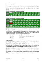
The video inputs are terminated within the equipment. The video outputs are single outputs on Q16
and Q32.
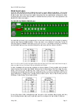
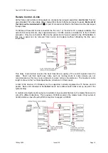
The Q16 (1U) Serial Video and Analog Video Frame
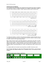
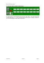
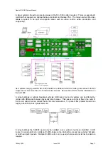
The Q32 (2U) Serial Video and Analog Video Frame
The 2U video frame shown above can also be used for unbalanced digital audio, refer to the audio
information later in this section.
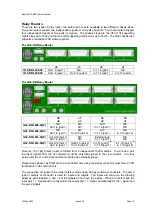
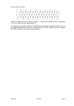
The 2U frame has an alarm connector used to report the status of the power supplies and control
processor. Each PSU and the controller have a relay with normally open contacts that are held
closed for a working system. Three contact pairs are provided as follows:
Pins 1, 2
Upper PSU
Pins 3, 4
Lower PSU
Pins 5, 6
Processor major error (Major Error LED, Reset)
Pins 7, 8
No connection
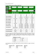
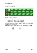
Video Reference
The Ref input is a looping input. Any video signal with standard syncs may be used as a reference
signal to determine when cuts are made during vertical (picture) blanking. Whilst a burst is not
required the use of colour black is the most commonly available signal and is preferred. This can be
looped through into a video input on composite video systems.
Mixed sync pulses of 2v amplitude may also be used. 4v pulses can be used but a modification is
required to the main video router module and involves the addition of a single 4.7K 5% resistor.
Note: If one of the looping input connectors is not used then a 75
Ω
terminator plug must be fitted on
the unused connector. Otherwise the level on the line will be twice that expected, and may cause
incorrect operation of other equipment attached to the line.
If no reference signal is connected then the unit will switch at random intervals at a rate of about
40Hz.


