background image


3

rd

 Generation Dual Channel 

Compact RDMS

TM

 Telemetry Receiver-Combiner 


10


Quasonix, Inc. 


3  Installation Instructions 

3.1  Mechanical 

The CRC™ is designed to be mounted by eighteen (18) 6-32 screws through the holes along the front and back 
edges, as depicted in Figure 4 on the following page. 

Pin assignments are listed in Table 4. 


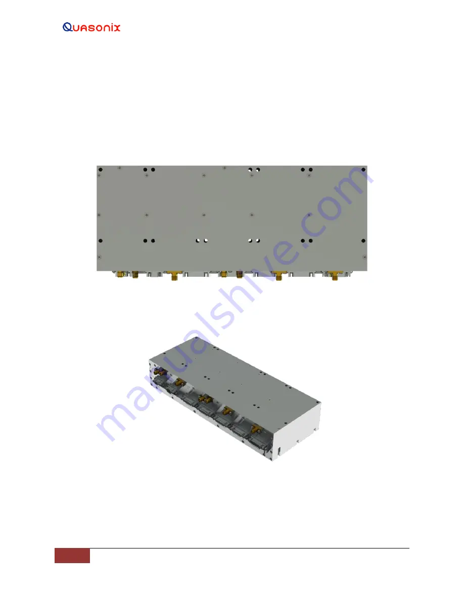
Figure 2: Mechanical Drawing 

– Top View (Dual-channel Connectors Shown) 


Figure 3: Dual Channel Compact RDMS Receiver-Combiner (CRC) 


Summary of Contents for Compact RDMS Telemetry Receiver-Combiner

Page 1: ...d Installation and Operation Manual 3rd Generation Dual Channel Compact RDMSTM Telemetry Receiver Combiner Quasonix Inc 6025 Schumacher Park Dr West Chester OH 45069 01 May 2022 Revision 1 0 Applies to RDMS System Version 19 3 Specifications subject to change without notice All Quasonix receiver products are under U S Department of Commerce jurisdiction categorized as 5A991 not covered by ITAR ...

Page 2: ...terbi Decoder for Legacy PSK Only K7 3 1 2 3 Band Configurations 5 1 2 3 1 Additional Band Codes 6 1 3 Package Contents 6 2 Specifications 7 3 Installation Instructions 10 3 1 Mechanical 10 3 2 Thermal 12 3 3 Electrical 12 3 3 1 CRC Front Panel Connections 12 3 3 2 Front Panel Connections 13 3 3 3 Electrical Signals 15 4 Operating Instructions 17 4 1 Power on Operation 17 4 2 Reset IP Address to D...

Page 3: ...e 37 5 4 2 3 Playback Demodulator 38 5 4 2 4 Data and Clock Polarity Settings 38 5 4 2 5 Data Quality Encapsulation DQE 39 5 4 2 6 Derandomizer Settings 41 5 4 2 7 Differential Decoding Settings SOQPSK Only 42 5 4 3 Configure Advanced Settings 42 5 4 3 1 Measured Bit Rate Setting 43 5 4 3 2 IF Filter 43 5 4 3 3 Output Muting 44 5 4 3 4 Muting Timeout 44 5 4 3 5 AFC Mode 44 5 4 3 5 1 AFC Mode Track...

Page 4: ...uired Legacy PSK modes only 57 5 4 12 Advanced PCM FM Settings 57 5 4 12 1 Modulation Index Scaling Mode 57 5 4 12 1 1 Modulation Scaling Track 58 5 4 12 1 2 Modulation Scaling Hold 59 5 4 12 1 3 Modulation Scaling Off 60 5 4 12 1 4 Modulation Scaling Acquire 61 5 4 12 2 Modulation Persistence 61 5 4 12 3 Mod Scale Index 62 5 4 12 4 Phase Noise Compensation 63 5 4 13 System Settings 64 5 4 13 1 An...

Page 5: ... 5 4 16 1 RSSI Display 81 5 4 17 Reset to Factory Defaults Button 82 5 4 18 Shutdown Hardware Button 82 5 4 19 Reboot System Button 83 5 4 20 Save Receiver Settings Button 83 5 5 Presets 84 5 5 1 Save Presets 84 5 5 2 Load Presets 88 5 6 About 89 5 6 1 Firmware Updates 90 5 6 2 Modify Network Settings 97 5 6 3 Monitor Page Default Update Rate 98 5 7 Footer Tool Bar 98 5 7 1 Help 98 5 7 2 Page Acce...

Page 6: ...dix A Recommended AM and AGC Settings for ACU Interfaces 117 11 1 AM and AGC 117 11 2 AM AGC Compensation 117 11 3 Recommended Settings 117 12 Appendix B Phase Noise Compensation 119 12 1 Trellis Demodulation Basics 119 12 1 1 Trellis Demodulation Summary 120 12 2 Phase Noise Impact 121 12 3 Clock Jitter Impact 121 12 4 When to Use PNC 121 12 5 Know Your Transmitter 122 13 Appendix C PCM Framer De...

Page 7: ...ser Interface Tool Bar 21 Figure 13 Browser Interface Monitor Screen 22 Figure 14 Monitor Screen for RDMS with Only One Channel Available 23 Figure 15 Monitor Screen Partial Status Information Block when Combiner On 23 Figure 16 Monitor Screen Partial Status Information Block when Combiner Off 23 Figure 17 Signal Graph and Signal Indicators Windows 24 Figure 18 Example PCM FM Eye Pattern 24 Figure...

Page 8: ...gure Basic Settings Window SOQPSK Mode 42 Figure 49 Advanced Settings Window 43 Figure 50 Advanced Settings Window IF Filter Menu 44 Figure 51 Advanced Settings Window AFC Mode Menu 45 Figure 52 Advanced Settings Window Best Channel Selector Checked 46 Figure 53 System Block Diagram with Best Channel Selector 47 Figure 54 Advanced Settings Window Time Aligner Selection Checked 48 Figure 55 Advance...

Page 9: ...le Index with Edit Field 63 Figure 83 Advanced PCMFM Settings Window Phase Noise Compensation Drop Down Menu 63 Figure 84 System Settings Window 64 Figure 85 System Settings Antenna Controls 65 Figure 86 Antenna Controls Window HyperTrack Selection 66 Figure 87 Antenna Controls Window AGC Polarity Selection 66 Figure 88 Antenna Controls Window AGC Scale Selection 66 Figure 89 Antenna Controls Wind...

Page 10: ... Reset to Factory Defaults Button 82 Figure 121 Advanced Buttons Shutdown Hardware Button 83 Figure 122 Advanced Buttons Reboot System Button 83 Figure 123 Advanced Buttons Save Receiver Settings Button 84 Figure 124 Presets Option on Tool Bar 84 Figure 125 Presets Screen 84 Figure 126 Presets Screen Closeup of Left Side 85 Figure 127 Presets Screen Closeup of Right Side 85 Figure 128 Preset View ...

Page 11: ...Various Signal to Noise Ratios 105 Figure 159 70 MHz IF Module in 2 x 3 Chassis 108 Figure 160 70 MHz IF Module in 2 x 3 Chassis SAW Filter Responses Narrow Group 10 MHz Span 109 Figure 161 SAW Filter Responses Wide Group Plotted on 100 MHz Span 110 Figure 162 Optional SAW Filter Responses for 70 kHz to 6 MHz 111 Figure 163 Optional SAW Filter Responses for 14 MHz and 28 MHz 112 Figure 164 Ideal P...

Page 12: ...figuration Example 2 Table 2 Band Configuration Codes 5 Table 3 Connector Descriptions 12 Table 4 Front Panel Connector Specifications 13 Table 5 Normal Default Video Output Signals 50 Table 6 RDMS BER Specifications 103 Table 7 Band Configuration Codes 106 Table 8 Recommended AM AGC Settings 117 Table 9 PCM FM Factory Reset Values 125 Table 10 SOQPSK Factory Reset Values 126 Table 11 Multi h CPM ...

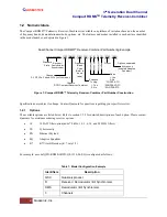
Page 13: ...light test station requirements The following waveform formats are supported by RDMS PCM FM ARTM Tier 0 SOQPSK TG ARTM Tier I ARTM CPM Multi h CPM ARTM Tier II Legacy PSK suite which includes BPSK QPSK Offset QPSK OQPSK Asymmetric QPSK AQPSK Unbalanced QPSK UQPSK Asymmetric Unbalanced QPSK AUQPSK Digital PM STC SOQPSK LDPC STC LDPC Of the aforementioned RDMS provides true multi symbol trellis demo...

Page 14: ... for assistance ordering receiver options 14 14 SAW filter option adds 70 kHz 1 4 3 6 14 and 28 MHz filters CS Cybersecurity EN Ethernet Payload EQ Adaptive Equalizer K7 K7 Viterbi Decoder k 7 rate 1 2 For example a model QSX RDMS 3RCD Q0 1110 00 EQ is configured as follows Table 1 Model Configuration Example Identifiers Description QSX Quasonix product R Receiver Demodulator Bit Synchronizer DMS ...

Page 15: ...rrive at the receiving antenna with different time delays carrier phases and relative strengths The sum of these multiple transmission paths can produce serious distortion and signal fading resulting in poor data quality and long periods of data outage Contrary to most situations increasing the transmit power will not improve the link quality and may actually make the situation worse Narrowing the...

Page 16: ... compatible with the convolutional encoding described in the Consultative Committee for Space Data Systems Recommendation for Space Data System Standards TM Synchronization and Channel Coding CCSDS 131 0 B 2 Section 3 Viterbi decoding is used to decode constraint length K 7 rate I 1 2 G2 inverted convolutional encoded data The purpose and benefits of convolutional encoding are similar to LDPC Howe...

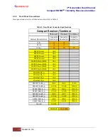
Page 17: ...e 2 Band Configuration Codes Freq Code A C E F G H J K L M P Q R S U W X Y Z Legend Frequency Gap Standard Base Frequency Range Extended Frequency Range available by selecting Extended Tuning 1 in part number P Lower L Upper L C 200 0 400 0 1150 0 1415 0 1435 5 1534 5 1585 0 1650 0 1750 0 1850 0 1855 0 4400 0 5150 0 5250 0 S 2185 0 2200 0 2394 5 2500 0 Base Base Base Base Base Extended Extended Ex...

Page 18: ...ge 0 075 MHz 20 MHz 70 MHz extended range Band Code T 2025 0 MHz to 2110 0 MHz standard range 1 3 Package Contents The contents of the box include the following Compact RDMS Telemetry Receiver Combiner 50 ohm terminators preinstalled on IF output MDM 25 IP Reset Default connector A copy of the Installation and Operation manual is included with the Browser Interface software Help option ...

Page 19: ...Bm 10 dBm for C band Available gain to 70 MHz IF output 114 dB Gain control 128 dB control range User selectable AGC or MGC AGC freeze AGC load impedance 1 KOhm AGC time constant Adjustable to any value from 0 1 ms to 1000 ms First IF bandwidth 60 MHz nominal IF rejection 90 dB Image rejection 70 dB RF input impedance 50 ohms VSWR 3 1 Max 2 1 Typical Second IF Section IF frequency 70 MHz IF output...

Page 20: ...25 kbps to 23 Mbps in BPSK 50 kbps to 46 Mbps in QPSK in 1 bps steps Synchronization time Average at BER 1e 5 Tier 0 250 bits Tier I 385 bits Tier II 2 800 bits Synchronization acquisition threshold Tier 0 8 0 dB Eb N0 RF Input dBm 118 0 1 Mbps 108 0 10 Mbps Tier I 6 0 dB Eb N0 RF Input dBm 116 0 1 Mbps 106 0 10 Mbps Tier II 7 0 dB Eb N0 RF Input dBm 117 0 1 Mbps 107 0 10 Mbps Synchronization drop...

Page 21: ...perature 20 C to 70 C Non operating Temperature 40 C to 85 C Operating Humidity 0 to 95 non condensing Vibration 20 G 5 Hz to 2 kHz all axes Acceleration 100 G all axes Shock 100 G pk half sine 5 ms all axes Altitude Up to 100 000 ft Physical Section Size Weight 10 31 x 4 00 x 1 92 80 oz Connectors RF input SMA female IF output SMA female Power and Ethernet MDM 9 Analog and Data MDM 25 Power 28 VD...

Page 22: ...anical The CRC is designed to be mounted by eighteen 18 6 32 screws through the holes along the front and back edges as depicted in Figure 4 on the following page Pin assignments are listed in Table 4 Figure 2 Mechanical Drawing Top View Dual channel Connectors Shown Figure 3 Dual Channel Compact RDMS Receiver Combiner CRC ...

Page 23: ...3rd Generation Dual Channel Compact RDMSTM Telemetry Receiver Combiner 11 Quasonix Inc Figure 4 3rd Generation Compact RDMS Receiver Combiner ...

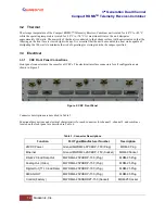
Page 24: ...C Front Panel Connections Front panel connectors are the same for all CRCs The electrical interface connectors for all configurations are shown in Figure 5 Figure 5 CRC Front Panel Connector descriptions are described in Table 3 Functional descriptions and electrical characteristics for each connector for channel 1 channel 2 and combiner located on the front panel are described in Table 4 Table 3 ...

Page 25: ...J6 J7 28VDC Power J8 4 28VDC Power J8 5 28VDC Power J8 8 28VDC Power J8 9 28VDC Return GND J8 1 28VDC Return GND J8 2 28VDC Return GND J8 6 28VDC Return GND J8 7 Ethernet RX_p J9 1 Ethernet RX_n J9 6 Ethernet TX_p J9 5 Ethernet TX_n J9 9 RS422 Clock A_n J10 1 J10 5 J10 9 RS422 Clock A_p J10 14 J10 18 J10 22 RS422 Data A_n J10 2 J10 6 J10 10 RS422 Data A_p J10 15 J10 19 J10 23 RS422 Clock B_n J10 3...

Page 26: ...12 18 J12 22 TTL Data A J12 2 J12 6 J12 10 TTL Data A GND J12 15 J12 19 J12 23 TTL Clock B J12 3 J12 7 J12 11 TTL Clock B GND J12 16 J12 20 J12 24 TTL Data B J12 4 J12 8 J12 12 TTL Data B GND J12 17 J12 21 J12 25 Ground J12 13 TTL HT_OUT AM J13 1 J13 3 J13 5 HT_OUT GND J13 14 J13 16 J13 18 AGC J13 2 J13 4 J13 6 AGC GND J13 15 J13 17 J13 19 TTL Dig 1 J13 7 J13 9 J13 11 TTL Dig2 J13 8 J13 10 J13 12 ...

Page 27: ...des a 70 MHz IF output for each channel for troubleshooting purposes These IF outputs are capped with 50 ohm terminators and these should be left in place unless another 50 ohm load such as a spectrum analyzer is connected instead Bit period 360 deg User asserts data on rising edge of TTL clock rising edge of ECL clock signal or rizing edge of TIA EIA422 A clock generator terminal Clock jitter and...

Page 28: ...ve a 50 Ohm load at all times If it is not connected to external test equipment then the 50 Ohm terminator metal cap that comes installed on the port must remain attached The IF input connector is only active if the correct part number is ordered The metal cap on the connector upon delivery is a dust cap only and is NOT interchangeable with the 50 Ohm termination on the IF output Do not remove dus...

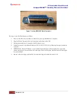
Page 29: ...a network or PC on the same subnet as the CRC Ensure that no other device on the network has the same IP address as the CRC 2 Apply power to the CRC via the Power connector Wait approximately 2 3 minutes before attempting to communicate with the CRC 3 Open a browser on a PC on the same Ethernet network The rack has an IP address assigned to it when the user sets it up If it is static the user must...

Page 30: ... the front of the CRC 3 Wait approximately one 1 minute for the IP address to reset 4 Attempt to connect to the default IP address 192 168 0 1 255 255 0 0 by following the steps described in section 4 1 5 IMPORTANT After the IP address is reset to default and confirmed via Browser Interface connection remove the IP Reset Connector from the Control port If this is left in place the IP address will ...

Page 31: ...en offers a quick snapshot of each rack mount receiver down to the channel level The screen is comprised of a table with columns for RDMS address Configuration Name Channel Frequency Mode Bit Rate signal strength S signal quality Q and lock detect status as text and as a red or green color block The user may access a specific unit by clicking on the Configure or Monitor button for any receiver lis...

Page 32: ...eration Dual Channel Compact RDMSTM Telemetry Receiver Combiner 20 Quasonix Inc Figure 9 Network Screen with Multiple Receivers and Active Channels Figure 10 Network Screen Closeup of Left Side Combiners Only ...

Page 33: ...up of Right Side 5 2 Monitor Screen The Monitor screen may be accessed via the Monitor buttons on the Network screen as described previously or via the Monitor option on the Tool bar as shown in Figure 12 Figure 12 RDMS Browser Interface Tool Bar The unit information displays in the Monitor view as shown in Figure 13 ...

Page 34: ...receiver settings such as frequency mode bit rate Signal indicators including lock detect signal strength signal quality best channel combiner link status Graphical representations of the spectrum Zero AGC button For user convenience this button displays on the Monitor screen and the Configure screen If the user is operating a single channel receiver only Channel 1 displays as shown in Figure 14 ...

Page 35: ... as Frequency Mode and Bit Rate is provided at the bottom of the display when the combiner is On as shown in Figure 15 or displayed in the center of the screen between Channel 1 and Channel 2 when the combiner is Off as shown in Figure 16 Figure 15 Monitor Screen Partial Status Information Block when Combiner On Figure 16 Monitor Screen Partial Status Information Block when Combiner Off ...

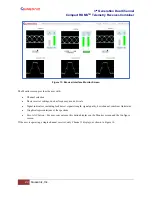
Page 36: ...ther display an eye pattern for PCM FM or a signal constellation for the other modes Figure 17 Signal Graph and Signal Indicators Windows An example of a PCM FM eye pattern is shown in Figure 18 An example of an SOQPSK constellation is shown in Figure 19 Figure 18 Example PCM FM Eye Pattern Figure 19 Example SOQPSK Constellation To the right of the Signal Graph is the Signal Indicators window show...

Page 37: ... to green at 10 dB Eb N0 and greater The measurement of strength from an incoming telemetry signal by itself does not provide enough information about the integrity of the received data Therefore the Data Quality Metric DQM is displayed to the right of the signal strength bar with Q above the graph It transitions from red being a zero 0 quality to green being a quality of 10 with 10 being the best...

Page 38: ...lative to AGC Zero The following bullets apply to RSSI Relative A value of zero indicates no input signal A value above zero indicates how strong the signal is above no input dBm displayed Figure 21 indicates AGC is not zeroed and the value is invalid Small r displayed next to the Signal Strength label indicates AGC Zero Relative was selected Figure 21 Signal Graph and Signal Indicators Windows Ze...

Page 39: ...ource image and a DQM graph display in the area between the two channels on the Monitor The Diversity Combiner with a signal lock is shown in Figure 23 Figure 23 Diversity Combiner Link with Locked Signal If diversity combiner is On any changes made to one channel will be copied to the other channel so that both channels are synchronized If diversity combiner is Off each channel is separate and se...

Page 40: ... to the left of the combiner Signal Quality Q status as shown in Figure 24 Figure 24 Best Channel Indicator Example Two status items display for the BCS First BCS Signal Quality is indicated with a color coded bar that indicates the data quality for the presently selected channel Numerical data quality is shown above the bar This indicator works just like the Combiner Signal Quality to the right o...

Page 41: ...st channel However many conditions may lead to selection of Channel 1 or Channel 2 as the best channel One common condition is multipath Another common and less intuitive condition is absence of any signal impairment In this case all channels have essentially perfect signal quality so the BCS cannot distinguish one that is best and will simply stick with its current selection until something chang...

Page 42: ...of the better signal and 0 of the worse signal Figure 27 Best Channel Indicator Ch 2 Figure 28 illustrates severe equalized multipath for Channel 1 and moderate equalized multipath for Channel 2 Note in this case the Combiner data quality is slightly better than Channel 1 but Channel 2 data quality is much better than the Combiner In this case the BCS selects Channel 2 as shown by the circled BCS ...

Page 43: ...lay Options The down arrow next to the Monitor option on the Menu Bar shown in Figure 30 enables selection of specific items to monitor while reducing bandwidth requirements The user may view Full Monitor screen Eye pattern or Constellation only PSD spectrum display only Combiner display only Examples of each display type are shown in the following figures Figure 30 Monitor Display Menu ...

Page 44: ...3rd Generation Dual Channel Compact RDMSTM Telemetry Receiver Combiner 32 Quasonix Inc Figure 31 Monitor Full Display Default Figure 32 Monitor Eye Pattern Constellation Display Only ...

Page 45: ...r screen are used to change in increments between low medium and high The user may press the Stop button to temporarily pause the screen transmission This has the effect of taking a snapshot in time freezing the page and is useful to more closely evaluate details such as a spectrum curve Network bandwidth usage is roughly halved as you progress through each setting from High to Low High is the as ...

Page 46: ...he Network screen as described previously or via the Configure option on the Header Tool bar as shown in Figure 36 Figure 36 RDMS Browser Interface Header Tool Bar All changes to configuration parameters are highlighted in green until the Send Settings or Refresh buttons are activated This is a visual reminder that something has changed 5 4 Combiner A pre detection diversity combiner is a standard...

Page 47: ... Modulation Scaling for both channels to be set to the same value However if Mod Scaling was set to Locked when the Frequency was changed Mod Scaling will change to Tracking 5 4 1 1 Frequency Diversity The Frequency Diversity option allows the user to independently change the frequency of each channel when the diversity combiner is On Click on the check box in the Frequency Diversity field to enab...

Page 48: ...ode Bit Rate Data and Clock Polarity Equalizer DQ Encapsulation and Derandomizer The Power Ratio control is available for UQPSK mode only A selection box displays below the Bit Rate option in UQPSK mode Refer to section 5 4 2 1 for specific information about Power Ratio Refer to section 5 4 2 2 for specific information about AQPSK mode Note The Equalizer is currently available for use with all mod...

Page 49: ...s message displays in the message area on the right side of the screen as shown in Figure 41 Other notifications display in red text on the right side Figure 41 Configure Screen Messages and Alerts 5 4 2 1 Power Ratio UQPSK Mode Only To properly distinguish the in phase I component from the quadrature phase Q component in a modulated UQPSK signal the demodulator requires knowledge of the ratio of ...

Page 50: ...ormal gain control provided by the RF front end AGC is unavailable when using the receiver as a playback demodulator Some IF input gain compensation is available but the input signal must be within the range 30 dBm 10 dB to obtain optimal performance Mod scaling Acquisition mode the default accurately determines the modulation index of a signal in the presence of additive white Gaussian noise AWGN...

Page 51: ...d per a standardized procedure DQM based on bit error probability BEP allows DQE from multiple vendors to interoperate The Quasonix DQM is based on statistics developed deep inside the demodulator Bit Error Probability BEP is the calculated likelihood that a bit is in error A very low BEP can be determined from only a few bits BEP does not require any known data and can be determined quickly and a...

Page 52: ... 00000E 08 43691 8 00 1E 09 1 00000E 09 49152 9 00 1E 10 1 00000E 10 54613 10 00 1E 11 1 00000E 11 60075 11 00 1E 12 1 00000E 12 65535 12 00 Figure 45 DQE Format Payload data is a user selectable length with a default of 4096 bits with the exception of STC mode where the default is 3200 bits and SOQPSK LDPC or STC LDPC mode where the default is the selected LDPC block size With a payload data leng...

Page 53: ...e it 0 10 5 4 2 6 Derandomizer Settings The Derandomizer defaults to Off Click on the drop down arrow to display the menu then select the desired option Figure 47 The standard running mode for non LDPC operation is IRIG The CCSDS option is only available when an LDPC Mode is enabled SOQPSKLDPC or STCLDPC or when Reed Solomon decoding is enabled IRIG Derandomizes data randomized using the IRIG 15 s...

Page 54: ...quires the differential decoder to be On The default value is On Differential encoding results in two differentially decoded bit errors for each received bit error This doubling negatively impacts subsequent error correction capability for block forward error correction Since the Attached Sync Marker used to identify block boundaries can also be used to resolve the phase ambiguity inherent in PSK ...

Page 55: ...proper IF filter is automatically selected based on the current mode and bit rate settings of the demodulator Although manual filter selection is available through the IF Filter Menu manual selection is not recommended In the case of a receiver with diversity combining enabled the two channels must have the same IF filter selected for proper operation The basic premise of trellis demodulation reli...

Page 56: ...econds The default value is 1000 5 4 3 5 AFC Mode The AFC Automatic Frequency Control Mode option shown in Figure 51 compensates for frequency offset in the received signal relative to the expected carrier frequency Demodulators for all modes in the RDMS contain frequency tracking loops that can accommodate some amount of frequency offset The amount of offset that can be tolerated depends on the m...

Page 57: ...ensate for the input frequency offset unless the input Eb N0 falls below a predefined threshold This mode is best suited for dynamic frequency offsets 5 4 3 5 2 AFC Mode Hold When AFC Mode is set to Hold the AFC holds its current compensation This mode is best suited for static frequency offsets It may be advantageous relative to the Acquire mode if the channel is initially known good but may beco...

Page 58: ... improvement over Channel 1 and Channel 2 individually However other impairments may cause the Channel 1 and Channel 2 signals to be uncombinable or to produce a suboptimal combined signal One simple example is frequency diversity with different multipath on Channel 1 and Channel 2 If the signal to noise ratio is equal on both received channels the combined signal will be composed of half of each ...

Page 59: ...y Encapsulation DQE for use by an external Best Source Selector BSS This capability allows spatial diversity across a vast range with a minimal number of BSS channels and attendant bandwidth Further since the BCS need only accommodate relatively miniscule latency differences between its inputs its local performance may exceed that of a BSS designed to handle several seconds of time delay between c...

Page 60: ...r to phase alignment time alignment is dynamic accommodating changes in relative target antenna positions over time When enabled the Time Aligner continuously measures skew between channels but remains in a monitor state with no timing correction as long as the skew remains below a predefined threshold When the skew exceeds the threshold the Time Aligner switches to a run state with full timing co...

Page 61: ...ck at twice the user bit rate in this configuration Select the desired encoding format from the drop down menu as shown in Figure 55 Figure 55 Advanced Settings Window PCM Encoding Drop Down Menu 5 4 5 Channel A Video Output The Channel A Video Output option shown in Figure 56 selects what signal appears on the I Video A output Normal Tape Out or Carrier Only The Normal output depends on the selec...

Page 62: ... Video B output Normal Tape Out or Carrier Only The Normal output depends on the selected Mode as shown in Table 5 Tape Out outputs the Pre D signal and Carrier Only outputs an unmodulated carrier either of these will be output at the carrier frequency selected by Tape Out Freq MHz Figure 57 Advanced Settings Window Channel B Video Output Drop Down Menu 5 4 7 Channel A Video Scale The Channel A Vi...

Page 63: ...s Alternatively any frequency up to 46 666 MHz may be entered as a custom frequency Note however that frequencies above 30 MHz will experience filter roll off and may not be useful Figure 60 Advanced Settings Window Tape Output Frequency 5 4 10 FM De emphasis PCM FM Mode Only The FM De emphasis option shown in Figure 61 is used to set the FM De emphasis value to NTSC PAL or Off This option should ...

Page 64: ...ndix 2 D LDPC encoding can have many benefits Its most common use is in range extension where bit errors occur due to a weak received signal LDPC can improve the point at which errors start to occur by over 9 dB This increase in link margin is equivalent to almost tripling the operating distance of the telemetry link Another application is error suppression for links like compressed video that suf...

Page 65: ...IRIG 106 17 Figures D 10 and D 11 Trellis synchronization under adverse conditions may be significantly faster than single symbol synchronization LDPC encoding is intended to improve performance specifically under harsh conditions which might have a negative effect on AFC tracking In general Quasonix recommends setting the AFC Mode to Off if possible This recommendation is especially important for...

Page 66: ...andwidth than all but the lowest rate LDPC codes and its error correcting performance is inferior to LDPC Therefore LDPC is the preferred forward error correction if possible The Viterbi Decoder control requires the K7 option and the RDMS must be set to one of the following PSK modes BPSK QPSK AQPSK AUQPSK OQPSK or UQPSK The Viterbi Decoder can be disabled or enabled by clicking on the check box i...

Page 67: ...r releases without the Convolutional Symbol control this was the only method supported The second method is for I and Q data to be created from the G1 and G2 generators respectively of a single convolutional encoder In this method only one convolutional encoder is used for both the I and Q data Figure 67 I and Q Data from Single Convolutional Encoder The appropriate decoder for this method is sele...

Page 68: ...Details of Reed Solomon encoding are presented in CCSDS 131 0 B 2 Section 4 The specific variant of Reed Solomon decoder implemented is the 255 223 code While Reed Solomon encoding can be used by itself it is a far less powerful code than LDPC Its primary use is as a second code to correct burst errors that arise in the Viterbi decoder The concatenation of Reed Solomon encoding and convolutional e...

Page 69: ...he desired value The valid range is 1 to 8 5 4 12 Advanced PCM FM Settings The Advanced PCM FM Settings window is shown in Figure 70 When the modulation is set to PCM FM the Scale Settings window includes settings for modulation scaling indexes In any other mode the Scale Settings are not available Figure 70 Advanced PCMFM Settings Window 5 4 12 1 Modulation Index Scaling Mode Modulation Scaling i...

Page 70: ...Acquire unless the unit was powered off from a preset condition If the unit was powered off from an unmodified preset setting then the default condition of Modulation Scaling is as defined in the preset When Track is set the modulation scale index is actively being tracked Note The active setting is not saved when the receiver is powered off unless the Mod Persist option was set to On Frequency mo...

Page 71: ... scaling operation functions independently in each channel 5 4 12 1 2 Modulation Scaling Hold When the RDMS has a good lock on the target transmitter Modulation Scaling should be set to Hold by selecting the Hold option on the Advanced PCMFM Settings Window Modulation Index Scaling Mode drop down menu as shown in Figure 74 When Modulation Scaling is set to Hold the Mod Scaling indicator on the Mon...

Page 72: ... set to Tracking Off or Acquire If the Locked index number is to be retained following a power off cycle of the rack then turn on the Mod Persist option in the Advanced PPCM FM Settings screen Refer to section 5 4 12 2 Modulation Persistence 5 4 12 1 3 Modulation Scaling Off The Mod Scaling Off setting is shown in Figure 76 When Modulation Scaling is set to Locked the Mod Scaling indicator on the ...

Page 73: ... to Armed In Armed state modulation scaling operates continuously Figure 78 Advanced PCMFM Settings Menu Modulation Scaling Acquire Figure 79 Monitor Screen Mod Scaling Set to Acquire If the receiver is locked and the delta h the change in modulation index has settled below the delta h threshold for the specified settling time the state changes to Triggered and in Triggered mode the estimated h mo...

Page 74: ...uld be turned off when a new generation digitally synthesized transmitter is the source Digitally synthesized transmitters do not have a variable deviation sensitivity adjustment and as such are not subject to inaccurate modulation index settings Acquire mode has two states Armed and Triggered When Modulation Scaling is set to Acquire the state is set to Armed In Armed state modulation scaling ope...

Page 75: ...vanced PCMFM Settings Window Modulation Scale Index Current Value Read Only Figure 82 Mod Index Scaling Mode Hold Modulation Scale Index with Edit Field To clear any held modulation scale index number go to the Main Menu and toggle the Mod Scaling option back to Tracking After Mod Scaling is set to Tracking the modulation index follows the receiver s present estimate of the mod index 5 4 12 4 Phas...

Page 76: ... System Settings window shown in Figure 84 includes the following settings Antenna Controls Clock Data Output Controls Test Utilities Figure 84 System Settings Window 5 4 13 1 Antenna Controls The Antenna Controls section contains the following parameters for AGC Automatic Gain Control and AM as shown in Figure 85 ...

Page 77: ...king stability range based tracking bandwidth ability to track through strong interfering signals rejection of incidental AM e g from spinning test articles and optimal multi receiver tracking Enabling HyperTrack switches the AM AGC front panel output to all digital mode This mode requires a HyperTrack compatible ACU for proper operation and to take advantage of the performance improvements Disabl...

Page 78: ...the scale is set the more dynamic range the AGC output can represent but the lower its resolution will be The AGC output is calibrated to a load of 1 KOhm Operation into other load impedances will result in the effective AGC scale factor being higher or lower than expected For example suppose the AGC zero point is 100 dBm The AGC output will be 0 0 V when no input signal is applied When a signal o...

Page 79: ...e any AM frequencies between roughly 10 Hz and 100 Hz To change the AGC Time Constant type the new value in ms or use the up down arrows to scroll to the desired value Figure 89 Antenna Controls Window AGC Time Constant Selection 5 4 13 6 AGC Freeze The AGC Freeze option disables the hardware gain compensation loop such that gain from the RF input to the IF output is fixed The receiver front end b...

Page 80: ... AGC holds its zero level after any frequency or IF bandwidth change or after a power cycle The AGC Zero mode manual hold or hold and save remains set if a waveform mode changes Figure 91 Antenna Controls Window AGC Zero Hold Drop Down Menu 5 4 13 8 AGC Compensate The user may enable AGC Compensation by clicking on the check box Refer to section 11 Appendix B for more information about the AGC Com...

Page 81: ...Hz to a lower frequency range known as P band 400 MHz 1150 MHz using an LO frequency of 5550 MHz This results in two issues that are addressed by the downconverting antenna control 1 Spectral Inversion In a downconverting antenna the LO is higher than the RF high side injection and the lower side band result is selected the spectrum is inverted All C to P band downconverting antennas are assumed t...

Page 82: ...ssumed there is no downconverting antenna The receiver is tuned to the actual P band frequency and the automatic spectral inversion is disabled 5 4 14 Clock Data Output Controls The Clock Data Output Controls section contains parameters for clock and data output for Channel A and Channel B as shown in Figure 94 Figure 94 Output Controls Window The Channel A Output options shown in Figure 95 select...

Page 83: ...nabled checked on the Configuration Basic Settings window the output is encapsulated otherwise it is not No DQE Selecting No DQE bypasses data quality encapsulation Test Data Selecting Test Data causes the output of the Data Generator to display on Channel B clock and data Figure 96 Output Controls Clock Data Output Channel B 5 4 15 Test Utilities The Test Utilities selections accessed via the Adv...

Page 84: ... desired Eb N0 Since the bit error rate of an ideally modulated signal at any given Eb N0 is known and should be readily reproducible the Noise Generator may be used to verify transmitter or receiver RF integrity Two parameters are available Test Noise and Noise Level Test Noise Enables or disables the AWGN generator as shown in Figure 98 Figure 98 Test Utilities Noise Generator Test Noise Drop Do...

Page 85: ...ed as known source data for system testing including transmitter or receiver RF integrity verification Optionally the user may invert data or add randomization The available parameters are Test Data Data Rate Pattern Inversion and Randomization Figure 100 Test Utilities Data Generator Test Data Enable or disable test data generation as shown in Figure 101 Figure 101 Data Generator Test Data Drop D...

Page 86: ... length PN15 Pseudorandom pattern 215 1 bits in length PN17 Pseudorandom pattern 217 1 bits in length PN20 Pseudorandom pattern 220 1 bits in length PN23 Pseudorandom pattern 223 1 bits in length PN31 Pseudorandom pattern 231 1 bits in length User defined User Defined A unique binary pattern between 2 and 32 bits specified by the person running the test only available when Pattern is User Defined ...

Page 87: ...the user to measure system performance It does this by comparing received data to a specified data pattern and counting the ratio of errored bits to total received bits This may be useful for various forms of system testing including transmitter or receiver RF integrity verification The Browser provides the ability to set BERT parameters and access BERT status information Figure 106 Test Utilities...

Page 88: ...ern that repeats based on the chosen pattern sequence a shorter pattern looks more regular a longer pattern looks more random PN6 Pseudorandom pattern 26 1 bits in length PN9 Pseudorandom pattern 29 1 bits in length PN11 Pseudorandom pattern 211 1 bits in length PN15 Pseudorandom pattern 215 1 bits in length PN17 Pseudorandom pattern 217 1 bits in length PN20 Pseudorandom pattern 220 1 bits in len...

Page 89: ...igure 111 BERT Time Bit and Error Limit Selections Bit Limit Sets a specific number of total received bits as shown in Figure 111 the measurement completes when the selected number of bits has been received Error Limit Bits Sets a specific number of bit errors as shown in Figure 111 the test completes when the selected number of errored bits has been received Gating Selects the action that occurs ...

Page 90: ...hronization loss Figure 113 BERT Restart on Resync Drop Down Menu 5 4 15 3 2 BERT Measurement Status BERT Status is only available via the Test Utilities screen in the Browser The Status information shown in Figure 114 displays measurements for Channel 1 Channel 2 and the Combiner if enabled when a BER test is running Figure 114 Test Utilities BERT Status Colored indicators are always grey when in...

Page 91: ... occurred Error Rate Bit error rate in scientific notation Update On Off button Freezes the state of the Status window for easy viewing but the test continues to run as prescribed in the BERT Settings limited or continuous An example of the Status screen when a BER test is running with bit errors is shown in Figure 115 Figure 115 Test Utilities Status During BER Test 5 4 16 Zero AGC Button Automat...

Page 92: ...d the lowest signal level that the receiver is likely to encounter c Activate AGC Zero under this condition by clicking on the Zero AGC button The AGC output voltage is set to zero volts DC at a time when the receiver input is at its minimum value This process ensures that the AGC output voltage will not cross through zero volts DC under normal operation To confirm AGC Zero view the Monitor screen...

Page 93: ...e 116 If Absolute was the RSSI Display selection for the channel the actual signal strength is displayed If Relative was selected the RSSI displayed is relative to AGC Zero The following bullets apply to RSSI Relative A value of zero indicates no input signal A value above zero indicates how strong the signal is above no input dBm displayed Figure 21 indicates AGC is not zeroed and the value is in...

Page 94: ... Buttons Reset to Factory Defaults Button 5 4 18 Shutdown Hardware Button The Shutdown Hardware button shown in Figure 121 sends a command to prepare the RDMS hardware for the removal of power All current receiver settings are saved to ensure the subsequent startup restores the receiver s state Remote access is disabled when this action is performed There is no remote command to restart the hardwa...

Page 95: ...er to perform a shutdown power up on a receiver Figure 122 Advanced Buttons Reboot System Button 5 4 20 Save Receiver Settings Button The Save Receiver Settings button shown in Figure 123 saves the current RDMS parameters For example the user may have changed a variety of parameters since the last shutdown power up of the receiver and does not want to lose the settings in the event of a power outa...

Page 96: ...a the Presets option on the Tool bar as shown in Figure 124 Figure 124 Presets Option on Tool Bar 5 5 1 Save Presets Accessed from the Presets option in the Tool Bar Saved Presets screen shown in Figure 125 allows the user to save and load settings stored on the RDMS receiver Closeups of the right and left side of the Presets screen are shown in Figure 126 and Figure 127 Figure 125 Presets Screen ...

Page 97: ...loseup of Right Side The Saved Presets screen contains a list of eight 8 saved setup files Files are accessed by clicking on the View Modify button next to the desired preset When the user clicks on a View Modify button the Preset View or Modify Preset screen opens as shown in Figure 128 The contents and layout of this screen is similar to the Configure screen ...

Page 98: ...en changing an existing preset Preset names are limited to 20 alphanumeric characters dots dashes and spaces Figure 129 Preset View or Modify Preset Screen Preset Name and Description Fields The settings can be configured by clicking on a check box to enable or disable an option clicking on a drop down menu and making a selection or in the case of Frequency and Bit Rate typing the number directly ...

Page 99: ...e the changes and redisplay the original settings Then click on the Save Settings button To save the current configuration as a preset click on the Save as a Preset button in the Browser Interface Configure screen A successfully saved message displays in the Message bar as shown in Figure 130 Figure 130 Preset View or Modify Preset Screen Information Successfully Saved Message When the user clicks...

Page 100: ... name field now displays Default to indicate the change took place This is shown in Figure 132 Figure 132 Preset View or Modify Preset Screen Preset Name Set to Default 5 5 2 Load Presets Loading a preset configuration is a quick way to set up an RDMS with specific settings The RDMS has eight 8 default configurations pre loaded and ready to use on the receiver As shown in the previous section the ...

Page 101: ... click on the green Load Preset button on the line containing the desired preset Figure 134 Presets Screen 5 6 About To access the System Information screen click on the About option on the Tool bar as shown in Figure 135 Figure 135 About Option on Tool Bar In addition to displaying the system information this screen is also used to add a Rack Alias if desired Type a new name into the Rack Alias f...

Page 102: ...Figure 136 System Information Screen Figure 137 System Information Screen Additional Information 5 6 1 Firmware Updates The CRC supports a remote Firmware Update via the browser interface This feature relies on an encrypted and signed firmware update file provided by Quasonix upon release ...

Page 103: ... firmware update file from Quasonix 2 Using a web browser navigate to the About page of the RDMS Browser Interface as shown in Figure 138 Figure 138 Browser Interface About 3 Next to the System Version parameter click on the Firmware Update Page link as shown in Figure 139 Figure 139 About System Version Firmware Update Link ...

Page 104: ...gure 140 Firmware Update Procedure and Notes 6 After the selected filename displays click on the Load Update File button to transfer the file to the RDMS Note Autostart may be selected before clicking on the Load Update File button to automatically start the update process after the upload is complete Click on the Autostart check box to select The upload process takes about 5 10 minutes depending ...

Page 105: ...1 Firmware Update Upload Status 7 After the file has been transferred review the updated Notes as shown in Figure 142 8 Click on the Begin Update button to start the update Note If Autostart was selected previously this step is automated No further input is required unless an error is encountered ...

Page 106: ...gure 142 Firmware Update File Selected Ready to Update Do not power off the RDMS during the update Do not close the browser window during the update During the update the status and approximate time remaining will display as shown in Figure 143 Figure 143 Firmware Update In Progress Status ...

Page 107: ... message displays indicating the RDMS Update has completed as shown in Figure 144 Figure 144 Firmware Update Complete Following the update the RDMS returns to normal operating mode and all parameters are reset to system defaults 10 Navigate to the About screen as shown in Figure 145 to verify that the System Version matches the firmware update version ...

Page 108: ...ation If the update fails for any reason an information screen displays as shown in Figure 146 Follow the instructions on the screen to retry the update or return to normal RDMS operation An error code is provided and should be noted for use in correspondence with Quasonix Figure 146 Firmware Update Failed Information Screen ...

Page 109: ...user On the About screen System Information a green Modify Network Settings button displays under the Interfaces portion of the screen as shown in Figure 147 Figure 147 System Information Screen Modify Network Settings Button Click on the Modify Network Settings button to display the Network Settings Page as shown in Figure 148 Figure 148 Network Settings Page ...

Page 110: ...to save the change A message displays to remind the user to manually restart the receiver A system restart is required for the rate change to take effect Resetting to Factory Defaults does not affect this setting Network bandwidth usage is roughly halved as you progress through each setting from High to Low High Update Rate is the as shipped default setting A user may change the frame reset rate t...

Page 111: ...on via multiple browser sessions that may be occurring on the receiver As noted earlier the 3rd Generation RDMS receiver uses a built in web server to provide monitoring and control Multiple users may access the receiver To minimize configuration or control conflicts the Browser Interface alerts users of potential conflicts Users may choose to override controls to provide access to specific pages ...

Page 112: ...ation This functionality may be useful to provide a record of settings used during test missions as a way to quickly switch between receiver setups or as a way to backup the receiver settings The files are saved locally based on the browser s default settings often the Downloads folder These files may be moved or renamed as needed Note modifying the contents of the files is not recommended While i...

Page 113: ...n Figure 155 Import Configuration Screen 1 Click on the Browse button to open a File Upload window on the desktop 2 Click on the Upload File button After the import file is selected the Import Configuration screen allows the selection of specific items to be immediately copied to the current device as shown in Figure 156 Note that any settings on the receiver in the selected areas will be overwrit...

Page 114: ...3rd Generation Dual Channel Compact RDMSTM Telemetry Receiver Combiner 102 Quasonix Inc Figure 156 Import Configuration Selection Window ...

Page 115: ...e Compact RDMS is capable of acquiring a signal with a frequency error of up to 100 kHz 6 3 Bit Error Rate The RDMS meets the following BER limits when tested with a signal source which complies with IRIG 106 17 Table 6 RDMS BER Specifications BER Maximum Eb N0 dB PCM FM Tier 0 SOQPSK TG Tier I Multi h CPM Tier II 10 3 7 5 9 5 11 0 10 4 9 0 11 5 12 5 10 5 10 0 13 0 13 5 10 6 11 0 14 5 14 5 Typical...

Page 116: ...ast reliable acquisition even at very low signal to noise ratio Synchronization time is a function of modulation type and IF frequency error Typical SOQPSK results from 10 000 synchronization trials are shown in Figure 158 1 E 08 1 E 07 1 E 06 1 E 05 1 E 04 1 E 03 1 E 02 1 E 01 1 E 00 2 3 4 5 6 7 8 9 10 11 12 13 14 Eb N0 dB BER Tier 0 QSX DMS 111 Tier I QSX DMS 111 Tier II QSX DMS 111 ...

Page 117: ...3rd Generation Dual Channel Compact RDMSTM Telemetry Receiver Combiner 105 Quasonix Inc Figure 158 Synchronization Time at Various Signal to Noise Ratios ...

Page 118: ...s 50 ohms Table 7 Band Configuration Codes Freq Code A C E F G H L M P Q R S U W X Y Z Legend Frequency Gap Standard Base Frequency Range Extended Frequency Range available by selecting Extended Tuning 1 in part number P Lower L Upper L C 200 0 400 0 1150 0 1415 0 1435 5 1534 5 1585 0 1650 0 1750 0 1850 0 1855 0 4400 0 5150 0 5250 0 S 2185 0 2200 0 2394 5 2500 0 Base Base Base Base Base Extended E...

Page 119: ...lemetry Receiver Combiner 107 Quasonix Inc 6 5 1 Additional Band Codes Two additional band codes are available Band Code 7 Through the IF Input 70 MHz through SAW filters 0 075 MHz 20 MHz 70 MHz Band Code T 2025 0 MHz to 2110 0 MHz standard range ...

Page 120: ...he measured responses of the eight filters are shown in Figure 160 and Figure 161 note the change of horizontal scale between the two figures Six additional filters are available allowing for a total of 14 The optional filters are 70 kHz 1 4 MHz 3 MHz 6 MHz 14 MHz and 28 MHz The measured responses of the optional filters are shown in Figure 162 and Figure 163 Contact Quasonix for information about...

Page 121: ...3rd Generation Dual Channel Compact RDMSTM Telemetry Receiver Combiner 109 Quasonix Inc Figure 160 70 MHz IF Module in 2 x 3 Chassis SAW Filter Responses Narrow Group 10 MHz Span ...

Page 122: ...3rd Generation Dual Channel Compact RDMSTM Telemetry Receiver Combiner 110 Quasonix Inc Figure 161 SAW Filter Responses Wide Group Plotted on 100 MHz Span ...

Page 123: ...3rd Generation Dual Channel Compact RDMSTM Telemetry Receiver Combiner 111 Quasonix Inc Figure 162 Optional SAW Filter Responses for 70 kHz to 6 MHz ...

Page 124: ...3rd Generation Dual Channel Compact RDMSTM Telemetry Receiver Combiner 112 Quasonix Inc Figure 163 Optional SAW Filter Responses for 14 MHz and 28 MHz ...

Page 125: ...er Combiner 113 Quasonix Inc 8 Maintenance Instructions The Dual Channel Compact RDMS Receiver Combiner requires no regular maintenance and there are no user serviceable parts inside Please consult the factory for any maintenance upgrade or repair requirements ...

Page 126: ...ect the functional operation of the Products At no time shall requests for changes in the software architecture or visual esthetics be considered a warranty item The Products are manufactured using new materials only Replacement parts may be new or equivalent to new Replacement parts are warranted to be free from defects in material or workmanship for thirty 30 days or for the remainder of the War...

Page 127: ...or sold by Quasonix or e by modification or service by anyone other than i Quasonix ii an Quasonix authorized service provider or iii your own installation of end user replaceable Quasonix or Quasonix approved parts if available for the Products in the servicing country THE TERMS OF THE WARRANTIES CONTAINED HEREIN DO NOT IN ANY WAY EXTEND TO ANY PRODUCT OR PART THEREOF OR SOFTWARE MATERIALS WHICH ...

Page 128: ...ded for return shipment Authorized return shipments must be addressed in the following manner Quasonix Inc ATTN Repair RMA 6025 Schumacher Park Drive West Chester OH 45069 To ensure that your shipment is processed most efficiently please include the following information with your product return Ship To Company name address zip code and internal mail drop if applicable Attention Contact person Nam...

Page 129: ...M AGC Compensation adjusts the AM output to neutralize these effects This allows the AGC to fully track out undesired AM at frequencies just below the antenna scan rate However the compensation adds a large amount of delay to the AM output proportional to the AGC time constant This delay may make antenna tracking difficult or impossible Therefore AGC Compensation should only be enabled when The an...

Page 130: ... set lower than recommended Setting the AGC Time Constant higher is unlikely to affect performance though it may degrade performance if vehicle dynamics cause relatively rapid changes in received signal strength The AM Bandwidth may be set lower to reduce noise on the AM signal or higher to reduce delay on the AM signal At the recommended settings AM phase delay is approximately 30 degrees for typ...

Page 131: ...cy in this bit below nominal data 0 Makes no use of adjacent symbols for error correction Trellis Detection Uses the phase tree for data detection Uses adjacent symbols to help decide on iffy bits Improves BER performance by 3 5 to 5 0 dB The Phase Tree shown in Figure 164 shows all of the possible paths the phase trajectory can take over a period of seven bits Figure 165 shows the two unique path...

Page 132: ... to help make better decisions about each individual bit This process improves BER performance by about 3 5 to 5 dB over conventional FM detection However this assumes that the transmitter is really following the known and correct phase tree and this assumption is NOT always true High phase noise can reduce the trellis detection gain because phase noise corrupts the tree The following figures illu...

Page 133: ...e integrated bit sync to lose lock Enabling the PNC mode opens the tracking loop bandwidth to accommodate for these issues This increase in bandwidth does have a tradeoff A wider tracking range allows the RDMS to deal with the additional jitter but it may also increase synchronization times slightly and slightly increase the minimum SNR at which the RDMS declares lock 12 4 When to Use PNC There is...

Page 134: ...ansmitter these tips can help determine when to use PNC If your transmitter was manufactured by these companies PNC should be OFF Quasonix guaranteed Nova Engineering highly likely L3 probably but digital transmitters only If the transmitter was manufactured by the companies below PNC should be ON Microwave Innovations Emhiser Southern California Microwave L3 analog transmitters ...

Page 135: ... Quasonix Receiver Analyzers can generate PCM frames using external user data or internal test patterns for the frame payload Within the Receiver Analyzer this functionality is referred to as the PCM Framer This note describes the detailed capabilities of the PCM Framer and Deframer 13 1 PCM Framer The PCM Framer supports fixed length PCM frame generation with the following parameters Major frame ...

Page 136: ...ber of bits early or late that the sync pattern may appear relative to other detected sync patterns and still be detected CORR_THRESH Number of bits of the sync pattern that must match to declare sync detect LOCK_THRESH Number of valid sync detects required to declare PCM frame lock SEARCH_THRESH Number of invalid sync detects required to declare loss of PCM frame lock once locked The PCM Deframer...

Page 137: ...000 MHz Table 9 PCM FM Factory Reset Values Parameter Reset State Parameter Reset State Bit Rate 1 Phase Noise Compensation Off Combiner if available Off Muting Timeout 1000 Clock Polarity Normal Output Muting Off Data Polarity Normal Downconvert Antenna Disabled Equalizer if available Off AGC Polarity Positive DQ Encapsulation if available Disabled AGC Scale 10 Derandomizer Disabled AGC Time Cons...

Page 138: ... Modulation Scaling N A Clock Polarity Normal Data Polarity Normal Derandomizer Disabled Differential Decoder Enabled IF Filter Auto Downconvert Antenna Disabled AGC Zero Mode Manual Convolutional Decoder N A Lock Output Polarity Active High NRZ Encoding N A Output Control Default Output Muting Disabled Phase Noise Compensation Disabled Tape Output Disabled ...

Page 139: ...te 1 Modulation Scaling N A Clock Polarity Normal Data Polarity Normal Derandomizer Disabled Differential Decoder N A IF Filter Auto Downconvert Antenna Disabled AGC Zero Mode Manual Convolutional Decoder N A Lock Output Polarity Active High NRZ Encoding N A Output Control Default Output Muting Disabled Phase Noise Compensation Disabled Tape Output Disabled ...

Page 140: ...dulation Scaling N A Clock Polarity Normal Data Polarity Normal Derandomizer Disabled Differential Decoder N A IF Filter Auto Downconvert Antenna Disabled AGC Zero Mode Manual Convolutional Decoder Disabled Lock Output Polarity Active High NRZ Encoding NRZ L Output Control Default Output Muting Disabled Phase Noise Compensation Disabled Tape Output Disabled ...

Page 141: ...it Rate 1 Modulation Scaling N A Clock Polarity Normal Data Polarity Normal Derandomizer Disabled Differential Decoder N A IF Filter Auto Downconvert Antenna Disabled AGC Enabled Convolutional Decoder N A Lock Output Polarity Active High NRZ Encoding N A Output Control Default Output Muting Disabled Phase Noise Compensation Disabled Tape Output Disabled ...

Page 142: ... operating system s Certificate Store The instructions for this vary by browser and are presented below 15 1 Firefox When using the Firefox browser in Windows the certificate must be imported through the Settings menu 1 Click on the Settings button in the upper right hand corner of the browser 2 Select Options The Options tab displays as shown in Figure 170 3 Select Privacy Security menu item 4 Cl...

Page 143: ... Authority file obtained from Quasonix then click on the Open button 7 The Downloading Certificate window displays as shown in Figure 172 Figure 172 Firefox Downloading Certificate Window 8 Click on the View button to examine the certificate It should match the one shown in Figure 173 9 Check the box for Trust this CA to identify websites then click on the OK button The certificate has now been im...

Page 144: ...emetry Receiver Combiner 132 Quasonix Inc Figure 173 Firefox Certificate Viewer Quasonix Root CA 10 Scroll through the Certificate Names in the Authorities tab of the Certificate Manager to ensure Quasonix Inc is in the list as shown in Figure 174 ...

Page 145: ... the RDMS 15 2 Edge Internet Explorer and Chrome To add a certificate to Edge Internet Explorer and Chrome use the Windows Certificate Browser tool After a certificate has been added to the system it is available for use in Edge Internet Explorer and Chrome 12 In Windows click on the Start Menu type Internet Options then press the Enter key to open the Internet Properties screen as shown in Figure...

Page 146: ...MSTM Telemetry Receiver Combiner 134 Quasonix Inc Figure 175 Internet Properties Content Tab 14 Click on the Certificates button The Certificates screen displays Click on the Trusted Root Certification Authorities tab as shown in Figure 176 ...

Page 147: ...act RDMSTM Telemetry Receiver Combiner 135 Quasonix Inc Figure 176 Certificates Screen 15 Click on the Import button to start the Certificate Import Wizard The Wizard is shown in Figure 177 Figure 177 Windows Certificate Import Wizard ...

Page 148: ...nix Root Authority file obtained from Quasonix Click on the Next button Figure 178 Windows Certificate Import Wizard Browse 18 Select Place all certificates in the following store 19 Click on the Browse button then select Trusted Root Certification Authorities When the Certificate Store parameter completes click on the Next button The Certificate Store screen is shown in Figure 179 ...

Page 149: ...Windows Certificate Import Wizard Choose Certificate Store 20 Click on the Finish button A message displays The import was successful Click on the OK button 21 View the list of Certificates under Trusted Root Certification Authorities and verify that Quasonix Root CA is listed as shown in Figure 180 ...

Page 150: ...el Compact RDMSTM Telemetry Receiver Combiner 138 Quasonix Inc Figure 180 Certificates Quasonix Certificate Imported 22 Using Edge Internet Explorer or Chrome browse to https RDMS_IP where RDMS_IP is the IP address of the RDMS ...

Page 151: ...hift Keying CCSDS Consultative Committee for Space Data Systems coding standard CD Compact Disk CPM Continuous Phase Modulation CRC Compact Receiver Combiner DB 9 D subminiature 9 pin Serial Connector DC Diversity Combiner DHCP Dynamic Host Configuration Protocol DPM Digital Phase Modulation DQ Data Quality DQE Data Quality Encapsulation DQM Data Quality Metric FPGA Field Programmable Gate Array I...

Page 152: ...eModulator Synchronizer RF Radio Frequency RJ 45 Ethernet Connection Jack RM Rack Mount RRC Remote RDMS Client RS 232 Recommended Standard 232 Serial Communications SAW Surface Acoustic Wave SDI System Degradation Indication SOQPSK Shaped Offset Quadrature Phase Shift Keying SOQPSK TG Shaped Offset Quadrature Phase Shift Keying Telemetry Group STC Space Time Coding TRL Tracking Loop TTL Transistor...

Reviews: