3
rd
Generation Dual Channel
Compact RDMS
TM
Telemetry Receiver-Combiner
30
Quasonix, Inc.
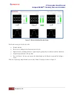
Figure 26: Best Channel Indicator-Ch 1
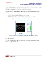
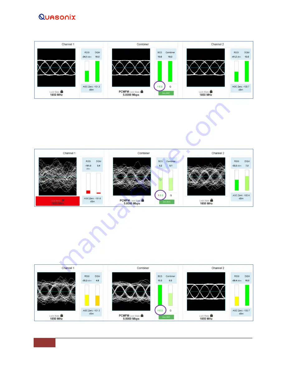
Figure 27 illustrates a bad signal for Channel 1, a good signal for the Combiner, with the best signal being selected
from Channel 2. This can happen if one received signal is so much better than the other that the combined signal is
composed of essentially 100% of the better signal and 0% of the worse signal.
Figure 27: Best Channel Indicator-Ch 2
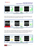
Figure 28 illustrates severe equalized multipath for Channel 1 and moderate equalized multipath for Channel 2. Note
in this case the Combiner data quality is slightly better than Channel 1, but Channel 2 data quality is much better
than the Combiner. In this case, the BCS selects Channel 2, as shown by the circled BCS selection indicator and
BCS data quality of 10. Without the BCS, the Combiner output data quality would be less than 6.
Figure 28: Best Channel Data Quality Better than Combiner Data Quality

