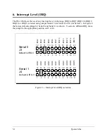
The DS-100 connects to peripheral equipment through male D-9 connectors. Adapters are
available to convert these connectors into standard D-25 male connectors. The standard serial
port connections are listed in Figure 14.
22
9
22
9
Ring Indicator
(RI)
4
7
5
8
Clear To Send
(CTS)
5
8
4
7
Request To Send
(RTS)
20
4
6
6
Data Set Ready
(DSR)
7
5
7
5
Signal Ground
6
6
20
4
Data Terminal Ready
(DTR)
3
2
2
3
Transmit Data
(TxD)
2
3
3
2
Receive Data
(RxD)
8
1
8
1
Data Carrier Detect
(DCD)
D-25
D-9
D-25
D-9
DCE Connection
DTE Connection
RS-232 Signal
Description
Figure 14 --- DS-100 connector definitions for EIA/TIA-232-E
1
2
3
4
5
6
7
8
9
10
11
12
13
20
21
22
23
24
25
14
15
16
17
18
19
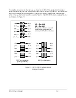
D-25 connector
(using adapter cable)
1
2
3
4
5
6
7
8
9
D-9 connector
(CN1 and CN2)
Figure 15 --- DS-100 Output connectors
DS-100 User’s Manual
6-3
Summary of Contents for DS-100
Page 7: ... This Page Intentionally Left Blank 1 2 Quatech Inc ...
Page 11: ...2 Double click on the Add New Hardware icon 3 2 Quatech Inc ...
Page 13: ...3 4 Quatech Inc ...
Page 14: ...3 5 Quatech Inc ...
Page 15: ...3 6 Quatech Inc ...
Page 16: ...7 Next select Ports COM LPT click Next 3 7 Quatech Inc ...
Page 21: ...11 Next Windows will begin the install the hardware click Next 3 12 Quatech Inc ...
Page 29: ... This Page Intentionally Left Blank 3 20 Quatech Inc ...
Page 38: ... This Page Intentionally Left Blank DS 100 User s Manual 6 4 ...
Page 42: ...DS 100 User s Manual Revision 4 21 March 2004 P N 940 0048 421 ...

