background image

Quatech SDS User’s Manual 


Introduction 

April 2008 

940-0183-155 

Page 3 

Using Port numbers 

In order for devices to communicate via a TCP connection or a UDP 

datagram, they must know each other’s IP address and port number. 
The SDS driver automatically sets the unit’s port number for you. 
A specific port number identifies each SDS serial port. An SDS 
assigns a port number of 5000 to the first port and then increments 

the port number sequentially for each subsequent serial port. SDS 

drivers must see the first port as IP address: 5000. 

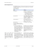
Identifying operating modes 

Normal, Tunneling, Raw TCP, Auto TCP, and Raw UDP are all 

different schemes to make a serial connection across a network using 
one or more Serial Device Servers.  

Normal mode 

If you use Quatech’s virtual COM port drivers or the IntelliSock™ 
SDK (see TCP socket services – IntelliSock™ on page 6), you should 

use the Normal mode to make your network connections. Normal 

mode is used in the vast majority of applications. Unless you are 
certain that you need to use a different mode, go ahead and configure 

your SDS in Normal mode. This mode allows for complete software 

control of the serial port by an application program.  

Tunneling mode 

Serial Tunneling allows two Device Servers and their Ethernet 

TCP/IP connection to act like a direct cable connection between two 
serial devices. No host computer is required.  
Tunneling is very simple to use. Use the SDS’ web interface to 

designate one SDS serial port as the tunneling master and the other 
SDS port as the tunneling slave. Configure the master with the serial 

port settings desired for the connection as well as the IP address of 

the tunneling slave. The master makes the connection and automatically 
configures the slave with the corresponding settings.  

Raw TCP mode 

In Raw TCP mode, serial port data travels over the TCP/IP 
connection without any protocol wrapper. You must configure the 

serial port settings using the SDS’ web interface. Raw TCP mode 

works with most third party universal serial device server drivers. 

Auto TCP mode 

Auto TCP mode is a special case of Raw TCP mode that allows the 

SDS to act as a network client and to initiate a TCP connection to a 
network host. You can configure the SDS so that it makes the 

connection in one of two possible instances:  

¾


It receives serial data (Data mode). 

¾


It sees that the DSR input is active (DSR mode).  

As with Raw TCP mode, you must configure the serial port settings 

using the SDS’ web interface. You must configure the SDS with the 

Note: You can think of the IP 
address as a telephone number 
and the port number as a 
telephone extension. 

Note: This information is 
useful for firewall configuration. 


Note: Normal is the standard 
connection mode for an SDS. 

Note: In Tunneling, a master 
sends out the configuration 

information to a slave so that 
the slave can communicate 
with it. 


Note: You could use Raw TCP 
if you were running a simple, 
custom TCP application. 


Note: Auto TCP is the only 
communication mode that lets 
an SDS initiate the connection. 

Summary of Contents for DSEW-100D

Page 1: ...Industrial Parkway Hudson Ohio 44236 5012 Toll free 1 800 553 1170 http www quatech com Quatech Device Server User s Manual P N 940 0183 155 Manual Revision 1 55 CONNECT WITH RELIABILITY Serial Devic...

Page 2: ...rmation in this manual is believed to be accurate and reliable at the time of posting Notwithstanding the foregoing Quatech assumes no responsibility for any damage or loss resulting from the use of t...

Page 3: ...anager 28 Win NT Changing port numbers 28 Uninstalling your SDS 29 Uninstalling from Windows XP 2000 29 Uninstalling from Windows NT4 29 Alternative installation steps 30 Configuring the SDS using the...

Page 4: ...etrieving Unit Configuration pop up box 20 Figure 13 TCP IP Network Configuration Parameters screen 21 Figure 14 Internet Protocol TCP IP Properties dialog box 22 Figure 15 Restart confirmation pop up...

Page 5: ...Serial Port Status screen 55 Figure 52 Serial Port Setup screen for Normal mode 56 Figure 53 Serial Port Setup screen for Tunneling mode 59 Figure 54 Serial Port Setup screen for Raw TCP mode 62 Figu...

Page 6: ...Introduction Quatech SDS User s Manual Page iv 940 0183 155 April 2008 This page intentionally left blank...

Page 7: ...nection is invisible to the application After following the simple steps included in the Quick Start Guide to attach your network and serial devices to the appropriate connectors on the Serial Device...

Page 8: ...ng a serial device through an SDS is that you can monitor and manage the device remotely even from across the world if you have authorization and the network connection is to the Internet Understandin...

Page 9: ...Use the SDS web interface to designate one SDS serial port as the tunneling master and the other SDS port as the tunneling slave Configure the master with the serial port settings desired for the conn...

Page 10: ...00 4 QSE 400 ESE 100 8 ESE 400 Quatech s SDS products all perform the same function see notes differing mainly in the number of serial ports available or in the serial protocol supported All D models...

Page 11: ...ystem Composed of managed devices on the network running the agent process such as an SDS Management Information Base MIB Standard organization scheme for storing data records an SDS device with a fir...

Page 12: ...t a security camera s serial port to an SDS a wireless PC can connect directly to the security camera through the SDS without ever going through an AP Before an SDS can communicate on an 802 11b g wir...

Page 13: ...t or return it to Quatech for service Step 3 Check the contents of the package to make sure you have received everything listed below SDS Power cable Power source Loopback connector s CD ROM containin...

Page 14: ...ct to your serial device s and can support RS 232 RS 422 or RS 485 connections They are located either to the left to either side of the Ethernet port or on the front panel depending on the model The...

Page 15: ...When the Status LED starts flashing slowly and before it starts flashing rapidly release the button The SDS then restarts automatically If the Reset button is held during the first 10 seconds of boot...

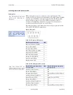
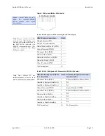
Page 16: ...ion DB 9 Data Carrier Detect DCD 1 Receive Data RxD 2 Transmit Data TxD 3 Data Terminal Ready DTR 4 Signal Ground GND 5 Data Set Ready DSR 6 Request To Send RTS 7 Clear To Send CTS 8 Ring Indicator RI...

Page 17: ...J 45 RS 422 485 signal description two wire mode Transmit Data TxD 1 Transmit Receive Data Data Auxiliary Output AuxOut 2 NC Auxiliary Output AuxOut 3 NC Signal Ground GND 4 Signal Ground GND Transmit...

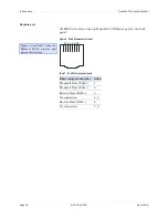
Page 18: ...ort on the back panel Figure 4 RJ 45 Ethernet port pinout 1 2 3 4 5 6 7 8 Table 7 RJ 45 Ethernet port signals Ethernet signal description RJ 45 Transmit Data TxD 1 Transmit Data TxD 2 Receive Data RxD...

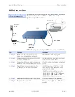
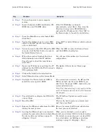
Page 19: ...r information Step 3 Connect an Ethernet cable between your Ethernet outlet and the SDS 10 100 port The Ethernet port is located on the back panel Step 4 Insert the power source jack into the power pl...

Page 20: ...u would a wired SDS but it will communicate via an access point on the 802 11b g network rather than through an Ethernet cable The SDS will scan all channels until it finds an AP at which time the Lin...

Page 21: ...and type the IP address for the SDS in the Web browser s URL address field The Quatech Device Server Home page displays Step 8 Click on Network in the selection bar Step 9 Select Infrastructure as the...

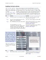
Page 22: ...art Run from the Task bar browse to the CD ROM drive and select the ThinQ exe file Click OK in the Run window to launch the installation The Quatech Serial Device screen displays followed by the Main...

Page 23: ...omputer using an Ethernet crossover patch cable If you cannot immediately attach the SDS to the target installation site temporarily attach it to the local hub or your computer s NIC for configuration...

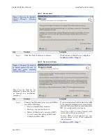
Page 24: ...lick the Next button to search for device servers The Search network for Serial Device Servers screen displays and the Wizard searches the local subnet for active serial device servers Continue with S...

Page 25: ...escription Step 12 Select one of two options The SDS is attached to the location where it will be installed and used The SDS is plugged into a temporary location for configuration purposes Choose this...

Page 26: ...hether the test passes or fails one of two screens displays TCP IP Network Configuration Parameters Network Connectivity Test Failed If the test passes the TCP IP Network Configuration Parameters scre...

Page 27: ...that server If not the SDS will default to the IP address 192 168 192 168 The Internet Protocol TCP IP Properties dialog box displays Continue with Step 17 If your address type is Static Address the I...

Page 28: ...server If you are not sure of the configuration parameters consult your system administrator Note For reliable operation we recommend a static IP address Continue with Step 18 Go to Step 19 Step 18 K...

Page 29: ...n The Information pop up box displays Continue with Step 21 Figure 16 Information pop up box Step Procedure Description Step 21 When the Status light glows green press OK The glowing Status light indi...

Page 30: ...ivity test pop up box displays Continue with Step 23 Figure 18 Rerun network connectivity test pop up box Step Procedure Description Step 23 Press the OK button to continue The Network Connectivity Te...

Page 31: ...hether the test passes or fails one of two screens displays TCP IP Network Configuration Parameters Network Connectivity Test Failed If the test passes the TCP IP Network Configuration Parameters scre...

Page 32: ...the device drivers that Quatech provides on the CDROM accompanying the SDS are signed but occasionally we must ship unsigned drivers In this case please be assured that we are working to sign the dri...

Page 33: ...the Quatech Device Manager Installation Wizard The wizard installs Quatech s Device Manager Follow the prompts Step 29 Win NT Win NT only Click Finish on the Installation Complete screen when the Dev...

Page 34: ...You can differentiate between SDS units using the MAC address which is equivalent to the serial number The Diagnostic Tools button runs a Ping test Use the Web Interface button to bring up the Web int...

Page 35: ...and Multi port serial adapters and select your Quatech Device Server 5 Right click and select Uninstall 6 At the Confirmation screen click OK 7 Click Finish at the Completing the Add Remove Hardware W...

Page 36: ...n If you do not need to change the configuration press the Next button to continue To change the configuration click the Reconfigure SDS button If your SDS is temporarily attached to your computer s N...

Page 37: ...ons I ve already moved the SDS to the remote subnet Press Next to continue I ll move the SDS later and run the wizard again Press Next to continue The Network Connectivity Test screen displays Go to S...

Page 38: ...from the DHCP server If you are not sure of the configuration parameters consult your system administrator Note We recommend that you use a static IP address to ensure reliable operation Continue wit...

Page 39: ...on pop up box Step Procedure Description Step 36 When the Status light glows green press OK This indicates that the SDS is ready Continue with Step 37 Step 37 Depending on your path to this step one o...

Page 40: ...operties The Rerun network connectivity test pop up box displays Continue with Step 39 The Internet Protocol TCP IP Properties dialog box displays Go to Step 32 Figure 30 Rerun network connectivity te...

Page 41: ...h the SDS may fail The SDS Wizard Information DHCP screen displays Continue with Step 41 If you answer No you return to the TCP IP Network Configuration Parameters screen Go to Step 16 Figure 32 SDS W...

Page 42: ...all from a list of all supported serial device server models Press Next to continue The Locate the Serial Device Server using direct discovery screen displays Continue with Step 43 The Locate the Seri...

Page 43: ...twork Interface Connection NIC on your computer Either a crossover patch cable or a straight through cable will work Continue with Step 44 Step 44 Connect power to the SDS and confirm that it is ready...

Page 44: ...ess Next to continue The SDS is set to use DHCP Press Next to continue Note If DHCP is disabled on the SDS press the Reset button on the back to enable it Neither of the above Press Next to continue T...

Page 45: ...device already on the target subnet Your system administrator should also be able to provide this information Step 47 Enter the target subnet s default gateway address in the space provided Press Nex...

Page 46: ...al subnet hub or switch Press Next to continue I ll connect the SDS directly to my computer Press Next to continue The Locate the Serial Device Server local discovery screen displays Continue with Ste...

Page 47: ...to the power source to the SDS Plug the connector of the unattached power cable into the power source s socket Plug the other end of the cable into a power outlet The SDS powers up Step 51 Confirm th...

Page 48: ...edure Description Step 53 Locate and highlight your SDS device Press the Next button to continue This screen shows a complete list of all currently available Quatech device servers The Specify IP Addr...

Page 49: ...ss screen Step Procedure Description Step 54 Enter the IP address for your SDS in the box provided Press the Next button to continue If you are not sure of the IP address see your system administrator...

Page 50: ...etest current configuration If you are not sure of the configuration parameters consult your system administrator The Internet Protocol TCP IP Properties dialog box displays Go to Step 32 Check with y...

Page 51: ...Once you have installed the drivers on your computer and established an Ethernet connection with the SDS you can maintain and configure the SDS using a Web interface Using a Web interface you can Conf...

Page 52: ...s URL address field The format for an IP address is http followed by a series of numbers separated by periods such as http 123 456 789 123 The Quatech Serial Device Server Home page displays Figure 4...

Page 53: ...f you are unsure of any of these settings See Setting TCP IP LAN and WiFi Wireless parameters below or see Setting SNMP parameters on page 52 Setting TCP IP LAN and WiFi Wireless parameters Step Proce...

Page 54: ...a unique address in your network Only let the DHCP server set the IP address if it is configured to always assign the same address to the SDS otherwise the connection will fail Note that the SDS MAC...

Page 55: ...Address mask A 24 255 0 0 0 B 16 255 255 0 0 C 8 255 255 255 0 Address mask Host bits 255 255 255 252 2 255 255 255 248 3 255 255 255 240 4 255 255 255 224 5 255 255 255 192 6 255 255 255 128 7 255 2...

Page 56: ...Step 7 For Ad hoc only configure the Channel As with the SSID devices sharing a wireless link must be tuned to the same channel Note The Channel setting is only used in Ad hoc mode In Infrastructure...

Page 57: ...displays You must reset the SDS for your changes to take effect If you press the browser s Back button your original settings remain unchanged Figure 44 IP Address Successful screen Step Procedure De...

Page 58: ...eft panel The SNMP Setup screen shown on the following page displays Figure 47 SNMP Setup screen Step Procedure Description Step 1 Enable or disable SNMP in the SDS Select the Enable SNMP checkbox to...

Page 59: ...send any traps Step 4 Enable or disable Security Check to allow the SDS to accept SNMP packets from any host in the same community group Clear the check box to allow the SDS to accept packets only fro...

Page 60: ...Address Update Successful screen Step Procedure Description Step 6 Click on the link to reset the SDS The Remote Reset screen displays Figure 49 Remote Reset screen Step Procedure Description Step 7 P...

Page 61: ...screen Setting serial port parameters In configuring your Serial Device Server s serial port parameters there are two main considerations Which operating mode should you use Is your serial port connec...

Page 62: ...Normal mode Step Procedure Description Step 1 Click on the serial port you want to configure Clicking on a port number highlights and selects that port The selections on the screen are automatically...

Page 63: ...oncerned about network traffic set this timer to a longer value Steps 4a through 4d apply only to RS 232 422 485 MEI units Step 4a MEI only Configure the serial port interface Click on the desired int...

Page 64: ...click Slave and leave the rest of the Operating Mode settings blank The slave waits for a master to connect to it and to provide the configuration parameters A master connects to one of a slave s ser...

Page 65: ...or Raw TCP Auto TCP and Raw UDP modes are in the following sections Step 3a Configure the Operating mode Click on the desired data Rate Multiplier Your choices are Auto Recommended Force X2 mode Force...

Page 66: ...oint your Slave ports are completely configured Master ports must have the following parameters set Step 3e Set the Baud Rate The SDS and the serial device s to which it is attached must use the same...

Page 67: ...igured for the Tunneling operating mode Setting Raw TCP operating mode parameters Raw TCP mode allows an application to communicate with an SDS without any custom protocol overhead In this mode the on...

Page 68: ...parameters for the selected port Step 2 Click on the Raw TCP operating mode selector Raw TCP allows an SDS device to communicate without any protocol overhead You will find directions for configuring...

Page 69: ...horter value If you are more concerned about network traffic set this timer to a longer value Step 3d Set the Baud Rate The SDS and the serial device s to which it is attached must use the same serial...

Page 70: ...on the Serial Port Setup page There is no way for the application to tell the SDS what to use for that serial port connection Auto TCP is also somewhat similar to Raw TCP in that only data passes thr...

Page 71: ...If you have an RS 232 422 485 MEI SDS the Configure Serial Port Interface step will display so that you can select between RS 232 and RS 422 485 operation If you have an RS 232 SDS the Configure Seri...

Page 72: ...g sections Directions for Raw UDP mode are in the following section Step 3a Configure the Operating mode Click on the desired data Rate Multiplier Your choices are Auto Recommended Force X2 mode Force...

Page 73: ...he SDS and the serial device s to stop the serial input output process Step 3i Click on the desired Auto TCP Mode selector Your choices are DSR Initiate the TCP connection when the SDS serial port s D...

Page 74: ...p 5 MEI applies to all units Step 4 non MEI or Step 5 MEI only Repeat the steps above for each port you need to configure and then press Save to implement all of your changes Close and re open the por...

Page 75: ...s with the selected address Step Procedure Description Preliminary Step Select Serial Ports from the selection bar Note Setup screens vary slightly between RS 232 and RS 232 422 485 MEI units If you h...

Page 76: ...e the Operating mode Click on the desired data Rate Multiplier Your choices are Auto Recommended Force X2 mode Force X4 mode Force X8 mode The auto setting has no effect on the baud rate you set Howev...

Page 77: ...od used between the SDS and the serial device s to stop the serial input output process Step 3i Set the UDP IP Address These are your options Multicast Broadcast Point to point This selection determin...

Page 78: ...x Tog to disable receivers and enable the transmit drivers only when the SDS is transmitting Step 4c MEI only Click on the desired connector setup Select Loopback All to internally loopback RTS and CT...

Page 79: ...unresponsive communications link Use this procedure to free a com port that locks up Note that the data trying to get through that port is lost and will need to be resent Running the Ping test Step Pr...

Page 80: ...Description Step 2 Press the Ping Test link to return to the Ping Test screen You can also press the Backspace key to return to the Ping Test screen Checking wireless status Step Procedure Descriptio...

Page 81: ...restrict this type of access to approved personnel only Once you create a user only someone using that user ID and password has Web access to the SDS Showing users Step Procedure Description Prelimin...

Page 82: ...ocedure Description Step 4 Enter the user name and password in the boxes provided If desired check the Remember my password box Be sure to key in the name and password in exactly as you did in the Add...

Page 83: ...selecting Show Users from the Admin screen See below Figure 65 Show Users screen Giving the SDS a descriptive name Step Procedure Description Preliminary Step Click on Admin in the selection bar The...

Page 84: ...ption Step 1 Browse to the location with the revised firmware file Most of Quatech s device drivers are available from our Web site Step 2 Press Send File The Remote Reset screen displays Figure 68 Re...

Page 85: ...een select Contact Us The Contact Us screen displays Figure 69 Contact Us screen Step Procedure Description Step 2 Click on either the sales or support Email links to contact the Sales or Technical Su...

Page 86: ...ble is properly connected to the serial device and to the SDS 3 Verify the cable pinouts 4 Try a different serial cable 5 Try a different port on the SDS 6 Review your serial device literature Make su...

Page 87: ...check the IP address of the PC by running ipconfig in a command box against the IP address of another PC plugged into the same hub as SDS 3 If the PC and SDS are on same subnet but a search still fail...

Page 88: ...n HyperTerminal b No Verify that the MAC address IP address Subnet mask and gateway address are correct for the SDS being used If not click on the Advance button and use the search utility to select t...

Page 89: ...drop strike or handle the SDS roughly Handle it like any other piece of sensitive electronic equipment Moving the SDS Follow these steps if you need to move your SDS or prepare it for shipment Discon...

Page 90: ...ctors W models e g DSEW 100 are equipped with 802 11b g wireless networking capability Hardware flow control Full modem control RS 232 EIA 232 RS 232 422 RS 485 RS 232 Serial ports RS 232 422 485 SSE...

Page 91: ...Data Data RTS 2 AuxOut N C DTR 3 AuxOut N C GND 4 GND Signal Ground GND TxD 5 TxD Transmit Receive Data Data RxD 6 RxD N C DCD 7 AuxIn N C DSR 8 RxD N C CTS 9 AuxIn N C N C 10 N C N C RS 232 signal Pi...

Page 92: ...of 30 V RS 232 or 15 5 V RS 422 485 and a peak energy dissipation of 0 1 Joules Note Units with the SS option are limited to 115 2 kbps due to capacitive loading Protocols and software Quatech provid...

Page 93: ...thernet connector Speed of network connection ON 100 Mbps OFF 10 Mbps Data Color RED if port is configured for RS 232 operation Color GREEN if port is configured for RS 422 485 operation Flashes when...

Page 94: ...er top cover Link left side of Ethernet connector Speed right side of Ethernet connector Data next to DB 9 serial port s Status next to power jack Power supply DC input with AC Adapters provided for 1...

Page 95: ...ght port RS 232 422 485 Serial Device Server with DB 9 connector s SSEW DSEW QSEW ESEW 100D One two four eight port RS 232 Serial Device Server with DB 9 connector s and WiFi capabilities SSEW DSEW QS...

Page 96: ...requirements a separation distance of at least 20 cm must be maintained between the antenna of this device and all persons Canadian Notice This device complies with Industry Canada ICES 003 regulatio...

Page 97: ...are is provided subject to the license agreement that is part of the package Customer agrees that it will be bound by the license agreement once the package is opened or its seal is broken Quatech doe...

Page 98: ...arranty or non warranty repair MUST be assigned a Returned Material Authorization RMA number prior to shipment This RMA number must be clearly marked on the exterior of the product s return packaging...

Reviews: