QUATRO
Air Technologies Inc.
Fresh Air Purifiers
-----------------------------------------------------------------------------------------------
Engineers Of Clean Air
4.0
MAIN SYSTEM COMPONENTS
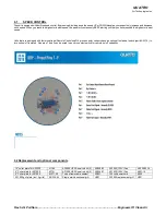
BLOWER ASSEMBLY: The blower is factory balanced and tested to ensure quiet, vibration-free operation.
CONTROL PANEL: Designed for easy monitoring, features micro-processor based control for speed variation and filter alarms.
5.0
SYSTEM SPECS
Description
AF2000
AF1000
Nominal Airflow (CFM/m3/hr)
1000 / 1700
600 / 1020
Dimensions, Height:
71” (1803mm)
52” (1321mm)
Dimensions, Width: *
24” (610mm)
22” (559mm)
Dimensions Length:
26” (660mm)
16” (406mm)
Voltage
120/1/60 or 230/1/50
120/1/60 or 230/1/50
Current:
5.4 or 2.3 amps
1.6 or 0.8 amps
Approx. Weight:
350lbs (159kgs)
200lbs (91kgs)
* -
add 2" for bend on power cord if req’d for width dimension
6.0
UNIT RECEIVING INSTRUCTIONS
Upon receipt, inspect unit for either visible or concealed damage. Damage should be immediately reported to the transport company. Ensure:
a)
All internal components are present and are adequately supported and installed;
b)
Labels and serial numbers are present for future identification;
c)
Verify that power supply is compatible with equipment. Also check that the unit is plugged into a grounded receptacle;
d)
Ensure that unit-mounted casters are tight and secure before manoeuvring the system.
e) Remove any spare filters supplied inside the unit and store for future use.
7.0
START-UP
a) Place unit on a flat surface, ensure filters are installed (see
Equipment Installation and Filter Maintenance Guide
on face of unit);
b) Ensure that supply and return air grilles are not obstructed in any way (air circulation patterns will be inhibited if airflow is obstructed);
c)
Insert male end of cord into the correct voltage circuit. Control will emit 3 beeps and 4 LEDs will flash along with those beeps.
d)
Press Power button and adjust airflow (speed control) accordingly. See Section 9.1.
WARNING: DO NOT OPERATE UNIT UNLESS ALL FILTERS ARE IN PLACE.
8.0
FILTER & BLOWER MAINTENACE
Proper maintenance is critical to extend the life of the system. The information presented below outlines basic maintenance procedures ensuring the
unit will provide trouble-free operation. The purifier is designed to allow quick access to the filters, blower/motor and control panel assembly.
Level
Type
Replacement Frequency
AF1000*
AF2000*
Level I
Dust Filter
Every 3 months
F007-8/box
F001-8/box
Level II
12” Intermediate Hi Capacity Filter
Every 6 months
F015-1/box
F014-1/box
or
6” Intermediate High Capacity filter
Every 6 months
F016
(2) F016
or
Intermediate General VOC/Odor Filter
Every 12 months
(1) F003-GPC
(2) F003-GPC
Level III
Hepa Filter (99.97%)
Every 12-18 months
F057-1/box
F052-1/box
or
Hepa Filter High Capacity (99.97%)
Every 12-18 months
F550-1/box
-
or
Hepa Filter (99.995%)
Every 12-18 months
F357
F352
* The filters shown are for the most popular filter sequences. Verify the part number on the filter in your system before ordering.
8.1
FILTER-ALERT SYSTEM AND FILTER REPLACEMENT
QUATRO has included in this unit a “FILTER ALERT” Warning System. When filters need to be replaced, the “Service Filter(s)” light (LED)
illuminates and beeper sounds for 2 seconds every 4 hours. When the appropriate
“Service Filter(s)” light (LED) Illuminates, it is time to replace
the filters following the above table. The information presented below outlines basic maintenance procedures ensuring the unit will provide
trouble-free operation for years to come.


