background image


QF1200S; edition 2016-05; page 4 of 24   


2. Description of the QF 1200S pump 


2.1. Appropriate use 

 
The Quattroflow 1200S is a 4-piston Diaphragm pump, which is mainly used to pump water-like fluids 
that are typically handled in research-, pilot plant- or production facilities of the pharmaceutical, 
biotech, food or cosmetic research centers or plants.  
Examples: 


Solutions containing proteins (albumin, IgG, Clotting factors, monoclonal antibodies, enzymes, 
vaccines.) 


Solutions of polymers or suspensions (silicon, latex, chromatography media) 


Cell suspensions  (bacteria, yeast, algae, fungi, mammalian cells) 

 Colloidal 

solutions 


Suspensions of viruses or phage 

 Dairy 

products 

 Gelatine 


Supplements and ingredients for cosmetic and food 


Typical applications for the QF 1200S 

 
- Filtration technology: 

  To recirculate feed/retentate (e.g. membrane cassettes, hollow fibre, spiral wound, ceramic 

elements)  


Feed pump for filter cartridges or plate and frame depth filters 

 
- Chromatography: 


Packing of chromatography columns 


Feed pump to mix gradients 

 
- Feed pump for centrifuges or separators 
 
- Feed pump for homogenizers 
 
- Feed pump for filling machines 


2.2. General description of the machine  

 
The Quattroflow 1200S pump is a 4-piston diaphragm pump. The four segments of the pump 
diaphragm oscillate back and forth. This alternate movement is created by a connector plate that is 
arranged on a ball bearing. The ball bearing sits on an eccentric shaft. The connector plate does not 
turn! 
 
The stroke of the pistons is determined by the angle of the eccenter. There are eccentric shafts with 5° 
and 3° available. The range of flow rates can be modified by changing the eccentric shafts. For the 
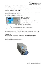
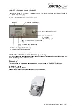
compact models with integrated controller please see chapter 2.4.  
 
Range of flow rate: 
5° eccentric shaft: approximate 20 -1200 L/hr (40 – 1200 L/hr for pumps with controller) 
3° eccentric shaft: approximate 10 - 800 L/hr (20 – 800 L/hr for pumps with controller) 
In gallon: 
5° eccentric shaft: approximate 5.3 - 317 gph (10.6 - 317 gph for pumps with controller) 
3° eccentric shaft: approximate 2.64 – 211 gph (5.3 - 211 for pumps with controller) 
 
The drive = motor + control needs to be chosen according to application.    


Summary of Contents for 1200S

Page 1: ...a are of a ope At d the w Orig and tructi 00S Qu Piston ultiple U eft hand and odel image m ersions are p l carefu an appr rating s ttentio warning inal In Insta ions uaterna Diaph Use with separa mid...

Page 2: ...ety instructions for maintenance inspection and mounting operations 10 3 7 Unauthorized reconstruction and spare part usage 10 3 8 Inadmissible modes of operation 10 3 9 Further warning and safety ins...

Page 3: ...and mechanical influences The following storage conditions are recommended Steady ventilated dust and vibration free storage room Ambient temperature between 15 C 59 F and 25 C 77 F with a relative hu...

Page 4: ...omatography columns Feed pump to mix gradients Feed pump for centrifuges or separators Feed pump for homogenizers Feed pump for filling machines 2 2 General description of the machine The Quattroflow...

Page 5: ...aOH can be applied The chosen cleaning agent can be recirculated and also stored inside the pump chamber For flushing out of any cleaning agent do not recirculate Check with appropriate analytical met...

Page 6: ...00S CV via the control panel Display show rpm V max speed 2 200 rpm Main switch Push to start the panel lights up Push to speed up arrow bottom up or to speed down arrow top down Push Green button RUN...

Page 7: ...ersonnel should change the parameter of the control panel on the back of the panel via DIP switches Attention Pay attention to the separate operating instructions of the ENGEL Motor QF1200S HT Pumpe M...

Page 8: ...we recommend the following steps 1 CIP of the pump chamber according to 2 4 or any other suitable process 2 Empty the pump 3 Remove the pump chamber from the pump drive see 4 1 1 4 Close in and outlet...

Page 9: ...strictly the safety guidelines of this manual as well as all national and possible internal regulations e g the handling of chemicals like caustic or acid the handling of biological materials the han...

Page 10: ...tart up and check the tightness of the pump o Please respect the relevant additional security advices if the pump has been used for aggressive dangerous or toxic liquids e g suitable protective equipm...

Page 11: ...the right tool for the specific application The user operator is responsible to perform a proper method of testing if the pump should be applied for his specific application The chemical and thermal c...

Page 12: ...led personnel Check the electrical cables before connecting to mains supply During all maintenance work it has to be ensured that no explosive atmosphere can arise Appropriate protection equipment is...

Page 13: ...rate SIP etc it may be necessary to shorten the maintenance intervals for the elastomers significantly In case that the diaphragm broke it needs to be replaced Then it is also recommended to check the...

Page 14: ...lves can be conducted by the operator The following drawings describe it step by step maintenance kit PSKITQF12MU In case of bursting diaphragms by overpressure we advice also to change the bearing un...

Page 15: ...he following torque values Image 10 Bolts pump chamber 10 Nm 7 4 lb ft Image 10 Bolts diaphragm cover housing 5 Nm 3 7 lb ft Image 12 Bolt clamping ring 6 Nm 4 4 lb ft Turn the pump chamber until you...

Page 16: ...eccentric shaft or Maintenance kit PSKITWLC125 5 eccentric shaft for QF1200S and QF1200S HT or Maintenance kit PSKITWLC125 CV QF1200S CV The replacement of the bearing unit can be conducted by the op...

Page 17: ...r 10 Nm 7 4 lb ft Image 9 Bolt clamping ring 6 Nm 4 4 lb ft gap 1 5 mm 0 079 0 118 inch 11 Turn the pump chamber until you see the screw of the clamping ring and fix it with 5mm hex key with a torque...

Page 18: ...h size10 remove screws 1 Dismounting drive house Fitting 4x M6 wrench size10 screws with washer 1 Mounting of drive house 4 3 Disassembly assembly of the drive housing For further questions and orderi...

Page 19: ...X Pressure line completely or partly clogged diaphragm maybe broken change diaphragm 10 X The diameter of the pipes in suction or pressure line are too small 11 X Check the coupling halves They must...

Page 20: ...pump Pump rpm motor rpm If reducer gear drives are used Pump rpm motor rpm x reduction ratio 6 1 Performance standard version Eccentric shaft 3 0 10 20 30 40 50 60 70 80 0 2 4 6 8 10 12 14 0 100 200...

Page 21: ...selected motor frequency drive combination the motor frequency and the resulting pump speed might differ 0 10 20 30 40 50 60 70 80 0 2 4 6 8 10 12 14 16 18 20 22 0 200 400 600 800 1000 1200 1400 0 500...

Page 22: ...ter t ct model w 0 psi 2 arts above w he final asse ct model w 0 psi 2 arts above w he final asse with integr 29 psi 58 ps were ascertai embly of the with integr 29 psi 58 ps were ascertai embly of th...

Page 23: ...pends on installation position ca 8 26 depends on inst position ca 8 26 depends on inst position ca 8 26 depends on inst position Product wetted surface approx cm inch 367 57 367 57 367 57 367 57 Spee...

Page 24: ...d into separate Control Box Power Supply Unit separate Controller integrated in pump Power Supply Unit integrated in pump Manufacturer standard Lenze AC tech TDK Lambda power supply Panasonic Mean Wel...

Reviews: