PiXtend V2 -L- Hardware Manual
All jumpers and pin blocks shown in the following pictures correspond to the factory setting
– i.e. the condition at delivery of the module!
–
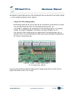
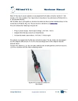
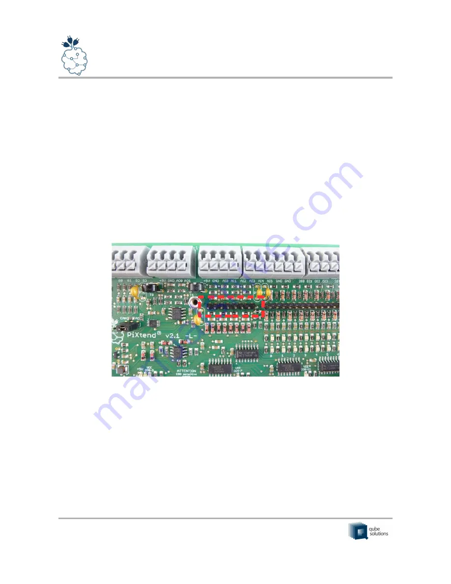
Jumper 5V / 10V (analog inputs)
Each analog input has two pins, which can be connected to each other by a jumper.
The two left pins belong to AI0, the two following belong to AI1, etc.
If no jumper is plugged in, the analog input is in measuring range 0..10 V (factory
setting). If a jumper is plugged in, the range of the input changes to 0..5 V.
The reduction of the voltage range can make sense if only small signals up to a
maximum of 5 V are to be measured. In this case, the full resolution is available for
the reduced measuring range.
If you are still unsure how high the voltage at the analog inputs can be, do not insert a
jumper and remain in the 0..10 V range.
www.pixtend.com
Copyright by Qube Solutions GmbH
45 / 146
Figure 30: Jumper - analog voltage inputs in
10 V range (factory default)


