background image

GB100CAU User Manual 

2. Product Overview

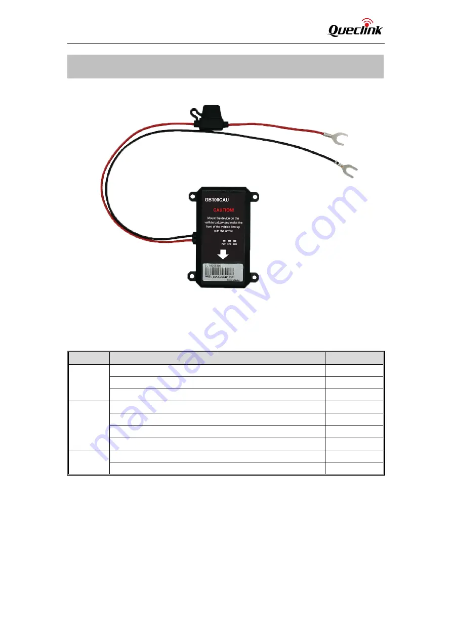
2.1. Product Appearance 

Figure 1. Appearance of GB100CAU 

2.2. LED Description 

Table 3. GB100CAU LED Description 

LED


Device Status 

LED Status 

PWR LED  The internal battery of device is in charge 

Fast flashing 

The internal battery of device is full 

On 

The internal battery of device is low 

Slow flashing 

GPS LED  GNSS is unfixed 

Fast flashing 

GNSS communication error, verification error or antenna error 

Slow flashing 

GNSS is fixed 

On 

GNSS chip is powered off 

OFF 

CEL LED 

The device is registering to network 

Fast flashing 

The device registers to network successfully 

Slow flashing 

Note:


1. Slow flashing: LED is about 200ms ON/1000ms OFF.
2. Fast flashing: LED is about 100ms ON/200ms OFF.

2.3. Parts List 

There is only the device. 

QSZTRACGB100CAUUM0100      

 3 

Summary of Contents for GB100CAU

Page 1: ...GV50MG User Manual GB100CAU User Manual EGPRS GPRS WCDMA LTE Cat 1 GNSS Tracker QSZTRACGB100CAUUM0100 Version 1 00...

Page 2: ...ermore system validation of this product designed by Queclink within a larger electronic system remains the responsibility of the customer or the customer s system integrator All specifications suppli...

Page 3: ...1 Product Appearance 3 2 2 LED Description 3 2 3 Parts List 3 3 Interface Definition 4 4 Getting Started 5 4 1 Opening the Case 5 4 2 Closing the Case 5 4 3 Installing SIM Card 6 4 4 Power Connection...

Page 4: ...GB100CAU User Manual 0 Revision History Version Date Author Description of Change 1 00 2020 06 03 Eddy Qi Initial QSZTRACGB100CAUUM0100 1...

Page 5: ...a wide variety of reports including emergency geo fence boundary crossings driving behavior low battery and scheduled and compressed GPS position reports 1 1 GB100CAU Products Table 1 GB100CAU Product...

Page 6: ...nternal battery of device is low Slow flashing GPS LED GNSS is unfixed Fast flashing GNSS communication error verification error or antenna error Slow flashing GNSS is fixed On GNSS chip is powered of...

Page 7: ...The GB100CAU has a 2 pin power cable The pin definition of the 2 pin power cable is as below Table 4 Description of 2 pin Power Cable Cable Colour Definition Comment Red VIN External DC power input 8...

Page 8: ...Figure 2 Opening the Case 4 2 Closing the Case Make sure the silicon rubber seal ring is in the gap of front case Put the power cable wire holder in the rubber groove of rear case Place the cover on t...

Page 9: ...r as shown below Close the SIM card holder and then close the case 4 4 Power Connection PWR pin 1 GND pin2 are the power input pins The input voltage range for this device is from 8V to 32V The device...

Page 10: ...evice to a reliable surface to prevent falling off Make the side with antenna face sky to have better signal reception Do not install the device under metal surface or in enclosed environments having...

Page 11: ...vice to a place under open sky It is better to make the side with antenna face the sky 6 2 Safety Info Do not disassemble the device by yourself Do not put the device in over heated too humid place an...

Page 12: ...erence by one or more of the following measures Reorient or relocate the receiving antenna Increase the separation between the equipment and receiver Connect the equipment into an outlet on a circuit...

Reviews: