background image

GL100 User manual                                                                    


2.


Product Overview 

2.1.

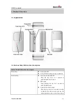
 Appearance


2.2.


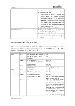
Buttons/Mini USB Interface Description 

Button /Mini USB Interface Description 

Power Key 

z


Turn on GL100 

z


Turn off GL100 (If power key is enabled). 

Function Key 

z


Geo-Fence mode (default) 

Press the key twice in 2 seconds to

enable/disable Geo-Fence0 

z


SOS mode 

Keep pressing the key for 3 seconds to 

enter the SOS mode 

z


Location Geo-Fence mode   

Press the key twice in 2 seconds to enable 

or disable Geo-Fence mode and use the 

current position as the centre of Geo-Fence 

TRACGL100UM002        


- 5 -   

Queclink

Confidential

Summary of Contents for GL100

Page 1: ...GSM GPRS GPS Tracker GL100 User Guide TRACGL100UM002 Revision 2 03 http www queclink com sales queclink com...

Page 2: ...on of this product designed by Queclink within a larger electronic system remains the responsibility of the customer or the customer s system integrator All specifications supplied herein are subject...

Page 3: ...ocol Commands History 13 4 4 An example to configure GL100 14 4 4 1 Set the parameters of main backend server 14 4 4 2 Set the parameters of secondary backend server 15 4 4 3 Set the parameters of sch...

Page 4: ...ange 2 01 2009 08 07 Moon XIE Initial 2 02 2009 12 09 Ella HUANG Update parameters of special function in chapter 4 4 5 2 03 2010 11 03 Ella HUANG 1 Add Chapter 4 4 8 and 4 4 9 2 Update parameters of...

Page 5: ...on can be real time or schedule tracked by backend server or specified terminals Based on the embedded Track protocol GL100 can communicate with the backend server through GPRS GSM network and transfe...

Page 6: ...power key is enabled Function Key z Geo Fence mode default Press the key twice in 2 seconds to enable disable Geo Fence0 z SOS mode Keep pressing the key for 3 seconds to enter the SOS mode z Location...

Page 7: ...call them Red LED 1 Green LED 1 Blue LED 1 and Red LED 2 Green LED 2 Blue LED 2 Light Color event State The power key has been pressed light Red The device receives a valid command light network sear...

Page 8: ...The blue led2 will be solid when the function key is pressed It will be off after the function key released User should press the function key for at least 3 seconds to start SOS report TRACGL100UM00...

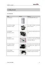
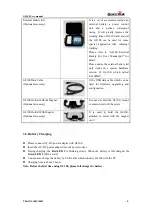
Page 9: ...sory It is used to attach the GL100 to belt Screw Driver Standard accessory It is used to twist off tighten the two screws on the side of GL100 when install SIM card Car Cigarette Charger Optional acc...

Page 10: ...which can be used for firmware upgrading and configuration GL100 Holder Without Magnet Optional accessory It is used to hold the GL100 mount to somewhere with the screw GL100 Holder With Magnet Option...

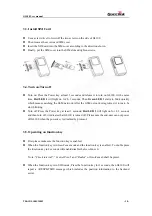
Page 11: ...inking z Turn off Press the Power key at least 3 seconds Red LED 1 will light on for 2 3 seconds and then turn off it indicates that GL100 is turned off Please note the end user can not power off GL10...

Page 12: ...elling But it is strongly recommended to establish a backend server and implement the way to control GL100 by SMS or GPRS Please refer to GL100 Track Air Interface Protocol for detail Before using the...

Page 13: ...ms Send All and Read All Send All is used to send the configuration message which is enabled in zone Function setting Read All is used to read all the parameters from GL100 and display in zone Functio...

Page 14: ...item Save Config File About Select About This Tool Then the following pop up window will display 2 State Display Display the state of operation including the serial port state baud rate state and the...

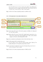
Page 15: ...selected the command message which shall be sent to GL100 will be generated based on input and displayed here Please note this command message can also be sent to GL100 through SMS or GPRS Step_3 It...

Page 16: ...able This Function is selected the command message which shall be sent to GL100 will be generated based on input and displayed here Please note this command message can also be sent to GL100 through S...

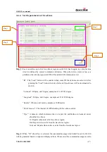
Page 17: ...be sent to GL100 through SMS or GPRS Step_3 It is recommended to read the parameters from GL100 and edit based on them Step_4 Set the Start Time the value range of HH is 00 23 The value range of MM i...

Page 18: ...tude 20bytes unit degree example as 31 187891 degree Longitude 20bytes unit degree example as 121 412248 degree Radius 10bytes unit meter example as 1000 meters Check Interval The interval of GPS chec...

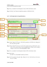
Page 19: ...SFR can be changed and the Send button is enabled Step_2 When Enable This Function is selected the command message which shall be sent to GL100 will be generated based on input and displayed here Plea...

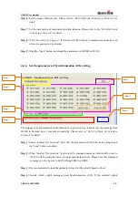
Page 20: ...rpose of Synchronization ACK function is to provide a way to make sure the message from GL100 to backend server was sent successfully Please refer to GL100 Track Air Interface Protocol for detail Step...

Page 21: ...ry Step_7 Click the Send button download the parameters of GTACK to GL100 4 4 7 Real Time Operation Step_1 Step_3 Step_2 Step_4 Step_1 Select Enable This Function after that the parameters of GTRTO ca...

Page 22: ...us of charger Please refer to chapter 3 3 3 for the report message RESP GTINF D Set whether to maintain GPS on for ever E Set the terminal name F Set whether to report the message RESP GTGSM including...

Page 23: ...tus of charging Info reported period 0 means disable report the terminal s information 1 1440 means the period of reporting and the unit is minutes Choice D is used to choose whether to maintain GPS o...

Page 24: ...RESP GTGSM Choice G is used to set the mask which is to control whether to report the event message Event Mask A numeric in hex style to mask the report message One bit represents a message Click Set...

Page 25: ...gh SMS or GPRS Step_3 It is recommended to read the parameters from GL100 and edit based on them Step_4 Set mode of google link function Please refer to GL100 Track Air Interface Protocol for detail S...

Page 26: ...sent to GL100 through SMS or GPRS Step_3 It is recommended to read the parameters from GL100 and edit based on them Step_4 Set call filter enable or disable in white call list function Please refer to...

Page 27: ...s in the internet Unable to power off GL100 The function of power key was disabled by AT GTSFR Enable the function of power key by AT GTSFR GL100 is turned on after insert a charging cable The functio...

Page 28: ...lease do not put the device on the overheating or too humid place avoid exposure to direct sunlight Too high temperature will damage the device or even cause the battery explosion z Please do not use...

Reviews: